
LM317 Adjustable PSU
LM317 Adjustable PSU is a runnable microcontroller simulation example on SensBench — open the wired circuit, inspect the code, and compile real firmware in your browser, no install needed. Last updated Aug 14, 2026.
FREE SIMULATOR EXAMPLE · INTERMEDIATE
LM317 Adjustable PSU
This example demonstrates the LM317 adjustable regulator on the Arduino Uno — R1 240 ohm and R2 720 ohm set the output to 5.0 V, and the ADC verifies the resistor math. One part, any voltage from 1.25 V to 37 V.
| Board | Arduino Uno (ATmega328P) + logic / power circuit |
|---|---|
| Difficulty | intermediate |
| Category | circuits |
| Libraries | None — just the Arduino core |
| Runs in | Sensbench browser simulator — free, no account |
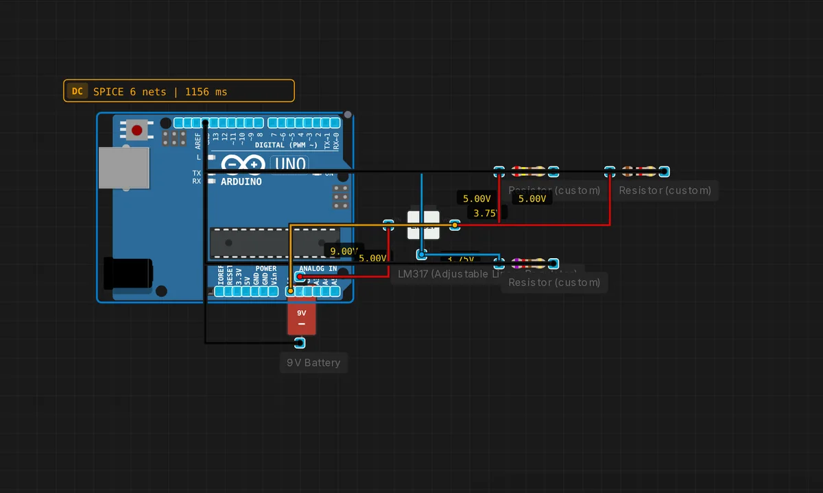
The exact circuit you get when you open this example — already wired, ready to run.
The sketch
// LM317 adjustable regulator
// R1 = 240, R2 = 720 -> Vout = 1.25 * (1 + 720/240) = 5.0V
void setup() { Serial.begin(9600); }
void loop() {
  float v = analogRead(A0) * 5.0 / 1023.0;
  Serial.print("LM317 Vout = "); Serial.print(v,2); Serial.println(" V");
  delay(500);
}
How it works
The LM317 is wired with its standard divider: R1 = 240 ohm from output to adjust, R2 = 720 ohm from adjust to ground, setting Vout = 1.25 × (1 + 720/240) = 5.0 V. The sketch reads the output on A0 every 500 ms and prints it — a live verification of the resistor math.
The printed value confirms the design: 5.00 V, computed entirely by the two resistor values. The example’s real lesson is the formula — pick any output voltage, solve for R2, and the LM317 delivers it. The 500 ms cadence catches the regulator’s settling and any load-induced droop.
Before you build it for real
The LM317’s minimum load current is 5-10 mA — below that, the regulator cannot hold regulation and the output drifts high. The reference current flows through the divider, which is why R1 is small (240 ohm): a large R1 starves the reference. Like all linears, it dissipates (Vin – Vout) × I as heat — dropping 24 V to 5 V at 1 A burns 19 W, impossible without a large heatsink, which is why the “1.25-37 V” range is only usable in pieces. And the output capacitors specified in the datasheet are not optional: the LM317 oscillates without them, showing a high-frequency ripple no ADC will catch.
Get the parts
Related examples
FAQ
Why use an LM317 when a 7805 does 5V?
The LM317 is adjustable: two resistors set any output from 1.25 V to 37 V, so one part replaces a drawer full of fixed regulators. The formula Vout = 1.25 × (1 + R2/R1) makes it a calculator problem to set 3.3 V, 9 V, 12 V — whatever the project needs.
What is the 1.25 in the formula?
The LM317 maintains a fixed 1.25 V between its output and adjust pins — its internal reference. The resistor divider scales that reference up: with R1 = 240 ohm and R2 = 720 ohm, the output becomes 1.25 × (1 + 720/240) = 5.0 V. Change R2 and the output follows the formula exactly.