
NPN Transistor LED Switch
NPN Transistor LED Switch is a runnable microcontroller simulation example on SensBench — open the wired circuit, inspect the code, and compile real firmware in your browser, no install needed. Last updated Aug 14, 2026.
FREE SIMULATOR EXAMPLE · INTERMEDIATE
NPN Transistor LED Switch
This example switches a high-current LED through a 2N2222 NPN transistor on the Arduino Uno — the MCU pin supplies only the tiny base current while the transistor carries the load. The classic transistor-as-switch pattern for anything bigger than a signal LED.
| Board | Arduino Uno (ATmega328P) + analog SPICE circuit |
|---|---|
| Difficulty | intermediate |
| Category | circuits |
| Libraries | None — just the Arduino core |
| Runs in | Sensbench browser simulator — free, no account |
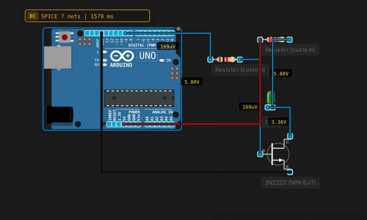
The exact circuit you get when you open this example — already wired, ready to run.
The sketch
// NPN switch — pin 9 drives base through 1k, collector drives LED
void setup() { pinMode(9, OUTPUT); }
void loop() {
  digitalWrite(9, HIGH); delay(1000);
  digitalWrite(9, LOW);  delay(1000);
}
How it works
Pin 9 drives the transistor’s base through a 1 kOhm resistor; the collector switches the LED to ground through the supply. When the pin goes HIGH, the base-emitter junction forward-biases at ~0.7 V, the transistor saturates, and the collector sinks the LED current. LOW on the pin releases the base and the LED goes dark.
The circuit inverts nothing — pin HIGH means LED on — but the current paths are split: the pin only sources the small base current (a few mA), while the LED’s current flows through the transistor from the 5 V rail. The sketch itself is a plain 1 Hz blink; the transistor is the whole lesson.
The 1-second on/off cycle gives the transistor clean transitions between cutoff and saturation — the two operating states that make switching circuits efficient. In between (the linear region) the transistor would dissipate heat, but a square drive avoids that.
Before you build it for real
The 1 kOhm base resistor is load-bearing: remove it and the pin fights the base-emitter diode — 5 V across a 0.7 V junction pulls dozens of milliamps and kills the ATmega328P’s output driver. The transistor’s current rating has a catch: 2N2222 collectors handle hundreds of milliamps, but the current must flow through a properly sized collector resistor — a power LED without one burns out. And the base needs at least ~0.7 V to turn on: driven from a 3.3 V MCU, the 1 kOhm base resistor still works, but the margins shrink. The simulator switches instantly; real transistors have switching delays that matter only above kilohertz PWM.
Get the parts
Related examples
FAQ
Why use a transistor when the pin can drive an LED directly?
The pin can drive ~20 mA safely; the transistor can switch hundreds of milliamps with the same pin current. When the load grows — power LEDs, relay coils, motors, LED strips — the transistor becomes the current-carrying switch and the MCU pin only supplies the tiny base current.
What does the 1k resistor do?
It limits the base current: (5V - 0.7V)/1k = 4.3 mA into the base. With the 2N2222’s gain of ~100, that controls up to ~400 mA of collector current. Without the resistor, the base-emitter junction would pull far too much current from the pin and destroy it.