
Inverting Amplifier (LM358)
Inverting Amplifier (LM358) is a runnable microcontroller simulation example on SensBench — open the wired circuit, inspect the code, and compile real firmware in your browser, no install needed. Last updated Aug 14, 2026.
FREE SIMULATOR EXAMPLE · INTERMEDIATE
Inverting Amplifier (LM358)
This example measures an LM358 inverting amplifier on the Arduino Uno — Rin 1 kOhm, Rf 10 kOhm, gain -10. The sketch prints input and output side by side so the inversion and the tenfold gain are visible in the numbers.
| Board | Arduino Uno (ATmega328P) + analog SPICE circuit |
|---|---|
| Difficulty | intermediate |
| Category | circuits |
| Libraries | None — just the Arduino core |
| Runs in | Sensbench browser simulator — free, no account |
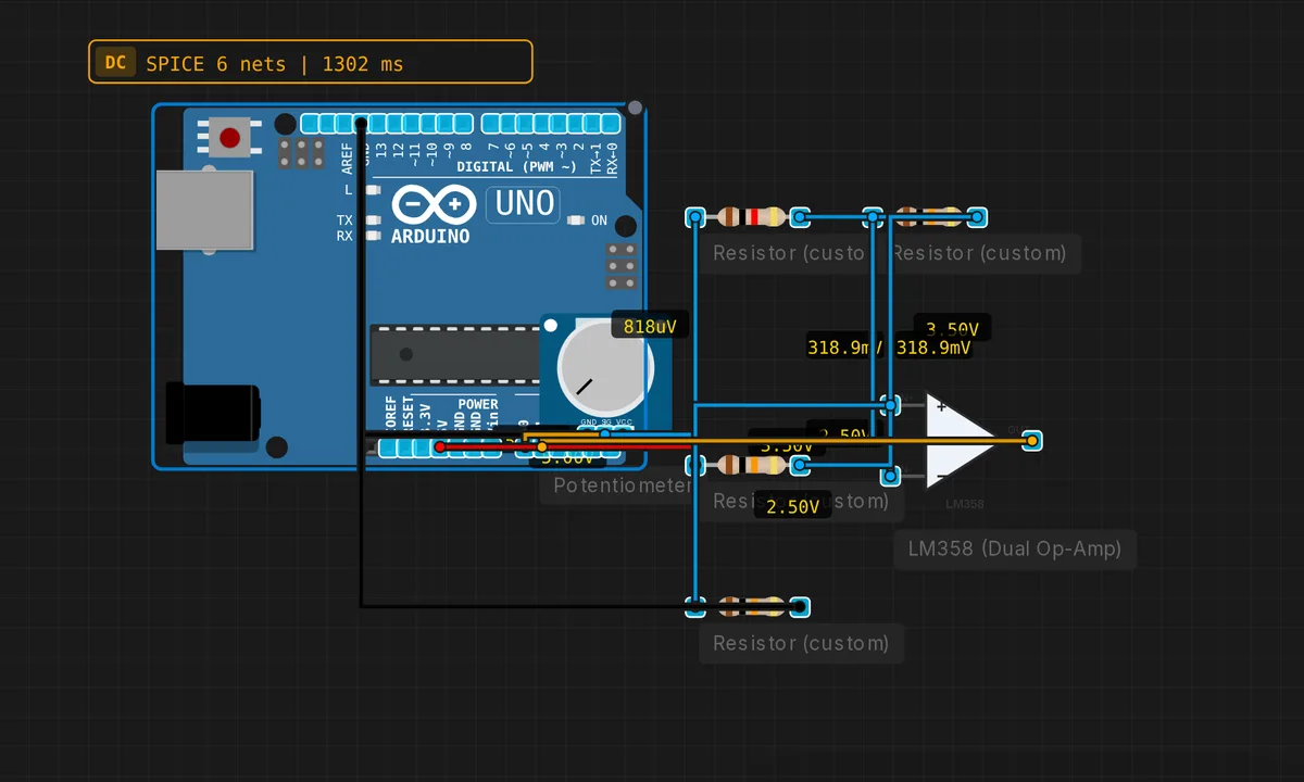
The exact circuit you get when you open this example — already wired, ready to run.
The sketch
// Inverting amplifier — gain = -Rf/Rin = -10
void setup() { Serial.begin(9600); }
void loop() {
  float vin = analogRead(A0) * 5.0 / 1023.0;
  float vout = analogRead(A1) * 5.0 / 1023.0;
  Serial.print("Vin="); Serial.print(vin,2);
  Serial.print(" Vout="); Serial.println(vout,2);
  delay(500);
}
How it works
The LM358 is wired as an inverting amplifier with Rin = 1 kOhm and Rf = 10 kOhm, giving gain = -Rf/Rin = -10. The sketch reads the input on A0 and the output on A1, prints both side by side, and the pair of readings demonstrates the relationship: Vout = -10 × Vin, within the rail limits.
The 500 ms polling is slow relative to the amplifier’s speed but right for reading steady values. The input and output prints together make the inversion visible: as Vin rises, Vout falls proportionally — the signature of the inverting topology.
Before you build it for real
The LM358’s output cannot reach the rails: it clips about 1.5 V below the supply, so with a 5 V rail the usable swing is roughly 0-3.5 V — a ±0.35 V input already saturates this gain-of-10 stage. The gain formula also ignores the op-amp’s finite bandwidth: at higher frequencies the gain rolls off, and the LM358 is a slow part (unity gain around 1 MHz, so gain-of-10 bandwidth is only ~100 kHz). And the inverting input means the input impedance equals Rin — just 1 kOhm here — so the signal source must be able to drive that load or the reading sags.
Get the parts
Related examples
FAQ
Why is the output inverted?
The inverting amplifier feeds the input through Rin into the op-amp’s inverting input, with feedback through Rf. The op-amp drives its output to keep the inverting input at virtual ground, so the output must swing opposite to the input. The gain is -Rf/Rin — negative means inverted, magnitude set by the resistor ratio.
What is virtual ground?
The non-inverting input is tied to a reference (often 0 V or mid-rail), and feedback forces the inverting input to match it — it sits at the same voltage without being physically grounded. Input current flows through Rin toward that point, and the output pulls through Rf to absorb it — that current balance is where the gain formula comes from.