
[Pico] I2C RTC Read
[Pico] I2C RTC Read is a runnable microcontroller simulation example on SensBench — open the wired circuit, inspect the code, and compile real firmware in your browser, no install needed. Last updated Aug 14, 2026.
FREE SIMULATOR EXAMPLE · INTERMEDIATE
[Pico] I2C RTC Read
This example reads the current time from a virtual DS1307 RTC over the Raspberry Pi Pico’s I2C bus at address 0x68. It requests the seven time registers, converts them from BCD, and prints a formatted time and date to the Serial Monitor once per second.
| Board | Raspberry Pi Pico (RP2040 dual-core Cortex-M0+, 133 MHz) |
|---|---|
| Difficulty | intermediate |
| Category | communication |
| Libraries | None — just the Arduino core |
| Runs in | Sensbench browser simulator — free, no account |
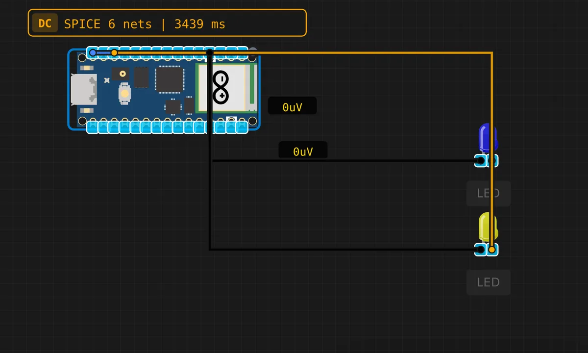
The exact circuit you get when you open this example — already wired, ready to run.
The sketch
// Raspberry Pi Pico — I2C DS1307 RTC Read
// Reads time from virtual RTC at address 0x68

#include <Wire.h>

byte bcdToDec(byte val) {
  return ((val >> 4) * 10) + (val & 0x0F);
}

void setup() {
  Serial.begin(115200);
  delay(500);
  Wire.begin();
  Serial.println("=== Pico I2C RTC Read ===");
  Serial.println("Reading DS1307 at 0x68 (system time)");
  Serial.println();
}

void loop() {
  // Set register pointer to 0
  Wire.beginTransmission(0x68);
  Wire.write(0x00);
  Wire.endTransmission();

  // Read 7 bytes: sec, min, hr, dow, date, month, year
  Wire.requestFrom(0x68, 7);
  if (Wire.available() >= 7) {
    byte sec   = bcdToDec(Wire.read() & 0x7F);
    byte min   = bcdToDec(Wire.read());
    byte hr    = bcdToDec(Wire.read() & 0x3F);
    byte dow   = bcdToDec(Wire.read());
    byte date  = bcdToDec(Wire.read());
    byte month = bcdToDec(Wire.read());
    byte year  = bcdToDec(Wire.read());

    const char* days[] = {"", "Sun", "Mon", "Tue", "Wed", "Thu", "Fri", "Sat"};

    Serial.print("Time: ");
    if (hr < 10) Serial.print('0'); Serial.print(hr); Serial.print(':');
    if (min < 10) Serial.print('0'); Serial.print(min); Serial.print(':');
    if (sec < 10) Serial.print('0'); Serial.print(sec);
    Serial.print("  Date: ");
    Serial.print(days[dow]); Serial.print(' ');
    if (date < 10) Serial.print('0'); Serial.print(date); Serial.print('/');
    if (month < 10) Serial.print('0'); Serial.print(month); Serial.print('/');
    Serial.print("20"); if (year < 10) Serial.print('0'); Serial.println(year);
  } else {
    Serial.println("RTC not responding!");
  }

  delay(1000);
}
How it works
The DS1307 keeps time in seven BCD registers starting at address 0x00: seconds, minutes, hours, day-of-week, date, month, year. The sketch writes 0x00 to set the register pointer, then requests 7 bytes with Wire.requestFrom(0x68, 7) and converts each one from BCD to decimal with the bcdToDec() helper.
The day-of-week byte is used as an index into a day-name array, so the output reads naturally: “Time: 14:03:22 Date: Thu 07/08/2026” style. The 1-second loop delay keeps the display ticking — every second a fresh read of all seven registers.
Before you build it for real
The DS1307 is a CMOS clock that wants battery backup: on real hardware, the time resets to 2000-01-01 whenever main power drops unless a coin cell is fitted on the module. The simulator models a continuously-running system clock, which hides this. Also, the DS1307’s timekeeping accuracy is about plus/minus 2 ppm at 25 C but drifts with temperature — a few minutes per month is normal. And it is a 5 V-tolerant chip: on a 3.3 V Pico bus, the pull-ups must go to 3.3 V, not 5 V, or the SDA/SCL lines will exceed the Pico’s input limits.
Get the parts
Related examples
FAQ
Why does the code convert BCD to decimal?
The DS1307 stores each digit of the time as 4-bit binary-coded decimal: 0x42 means 42, not 66. The bcdToDec() helper splits the nibbles and reassembles them as a regular number — (val >> 4) * 10 + (val & 0x0F). Skip this step and the clock reads nonsense.
Why mask the seconds with 0x7F and hours with 0x3F?
The DS1307’s register bits are overloaded: bit 7 of the seconds register is the clock-halt flag (CH), and the two high bits of the hours register select 12/24-hour mode. Masking strips those control bits so only the actual time digits survive the BCD conversion.