
PNP High-Side Switch
PNP High-Side Switch is a runnable microcontroller simulation example on SensBench — open the wired circuit, inspect the code, and compile real firmware in your browser, no install needed. Last updated Aug 14, 2026.
FREE SIMULATOR EXAMPLE · INTERMEDIATE
PNP High-Side Switch
This example switches a load from the high side with a 2N3906 PNP transistor on the Arduino Uno — pin LOW turns the load on, pin HIGH turns it off. It is the complement to the NPN low-side switch, for loads that must stay grounded.
| Board | Arduino Uno (ATmega328P) + analog SPICE circuit |
|---|---|
| Difficulty | intermediate |
| Category | circuits |
| Libraries | None — just the Arduino core |
| Runs in | Sensbench browser simulator — free, no account |
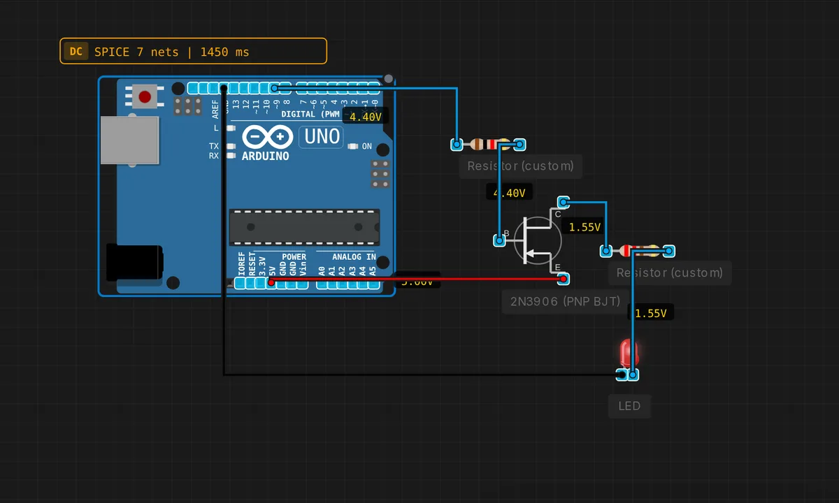
The exact circuit you get when you open this example — already wired, ready to run.
The sketch
// PNP high-side switch
// Pin 9 LOW = load ON, Pin 9 HIGH = load OFF
void setup() { pinMode(9, OUTPUT); }
void loop() {
  digitalWrite(9, LOW);  delay(2000); // ON
  digitalWrite(9, HIGH); delay(2000); // OFF
}
How it works
The 2N3906’s emitter sits on Vcc and its collector feeds the load. When pin 9 goes LOW, the base is pulled below the emitter through the base resistor, forward-biasing the junction, and the transistor conducts — Vcc flows to the load. Pin HIGH raises the base to the rail and the transistor cuts off.
The sketch drives pin 9 LOW for 2 seconds, then HIGH for 2 — ON then OFF, with the inverted logic documented in the comments. The 2-second phases give the circuit time to be observed in each state, and the comment line doubles as the mental model for reading the rest of the code.
Before you build it for real
The inverted logic is the trap: LOW = on, HIGH = off — copy this sketch into a project that assumes HIGH-on and the load behaves backwards. The PNP’s base must be driven through a resistor sized for the load current and gain; without one, the pin sinks the full base-emitter current at turn-on. And the high-side switch’s output is Vcc minus the transistor’s saturation drop — about 0.2-0.4 V lost — which matters for 3.3 V logic loads that cannot afford the loss.
Get the parts
Related examples
FAQ
Why use a PNP instead of the simpler NPN?
The NPN example switches the load’s path to ground — low-side. Some loads (motors, sensors with shared grounds, certain power rails) must stay tied to ground and be switched from the supply side — high-side. The PNP makes that possible: it connects the load to Vcc when the base is pulled low.
Why is the logic inverted?
A PNP conducts when its base is below the emitter. Pulling the base to ground (pin LOW) turns the transistor on; driving the base HIGH turns it off. The sketch’s comments spell this out — “Pin 9 LOW = load ON” — because the inversion surprises everyone the first time.