
STM32 Black Pill Blink
STM32 Black Pill Blink is a runnable microcontroller simulation example on SensBench — open the wired circuit, inspect the code, and compile real firmware in your browser, no install needed. Last updated Aug 14, 2026.
FREE SIMULATOR EXAMPLE · BEGINNER
STM32 Black Pill Blink
This example blinks the STM32 Black Pill’s onboard PC13 LED and prints a startup banner — the fastest way to prove the F411 toolchain works. It is the Black Pill’s equivalent of hello world, identical in shape to the Blue Pill blink but running on a faster Cortex-M4 core.
| Board | STM32 Black Pill (STM32F411, Cortex-M4, 100 MHz) |
|---|---|
| Difficulty | beginner |
| Category | basics |
| Libraries | None — just the Arduino core |
| Runs in | Sensbench browser simulator — free, no account |
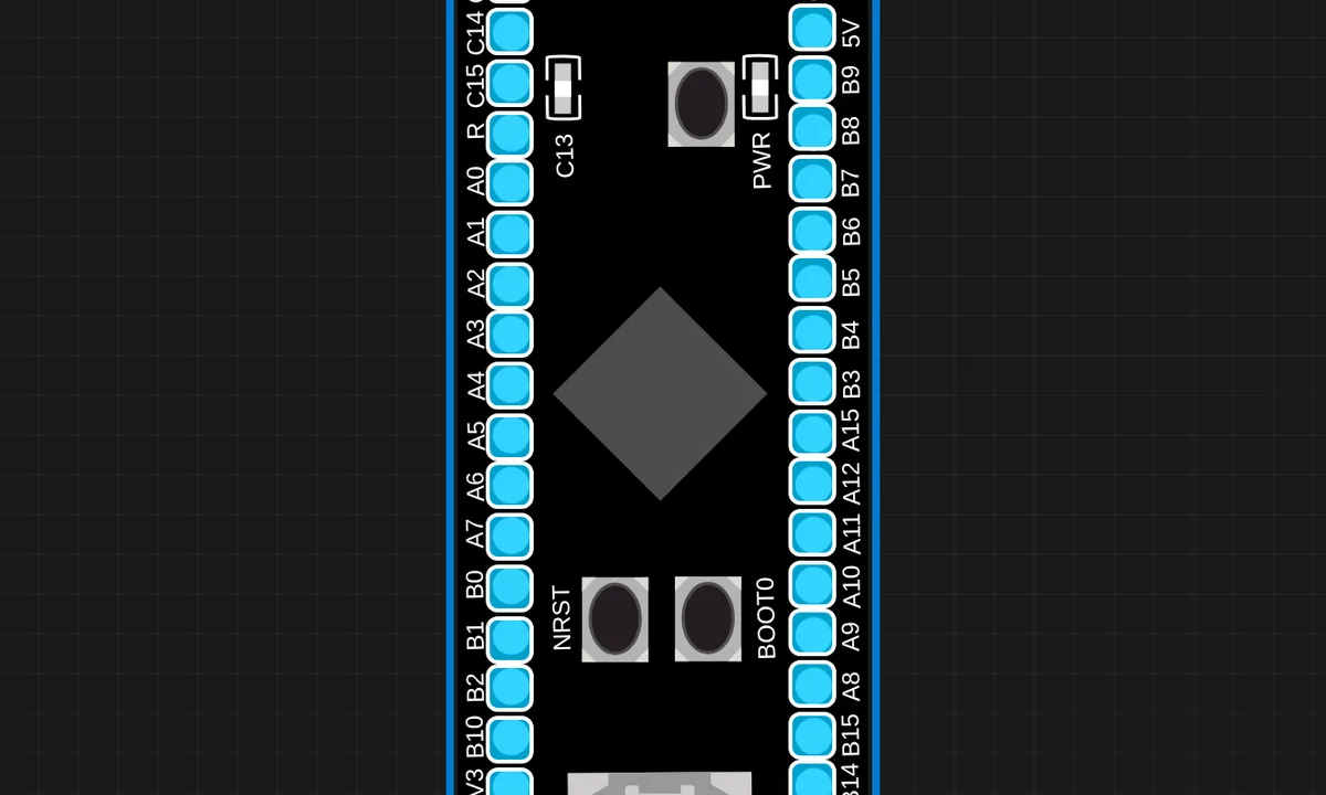
The exact circuit you get when you open this example — already wired, ready to run.
The sketch
// STM32 Black Pill (STM32F411CE, Cortex-M4) blink + serial.
// Onboard LED is on PC13 (active LOW).
void setup() {
  pinMode(PC13, OUTPUT);
  Serial.begin(115200);
  Serial.println("SENSBENCH Black Pill blink");
}

void loop() {
  digitalWrite(PC13, LOW);   // LED on (active-low)
  delay(150);
  digitalWrite(PC13, HIGH);  // LED off
  delay(150);
}
How it works
pinMode(PC13, OUTPUT) and the active-LOW toggling work exactly as on the Blue Pill: LOW lights the LED, HIGH turns it off. The loop blinks at 150 ms on, 150 ms off — faster than the Blue Pill example, showing the same code pattern at a different rhythm.
The Serial.println() banner in setup runs on USART1 at 115200. Under QEMU the Cortex-M4 core with FPU executes the same instructions, but floating-point support becomes available for sketches that need it — irrelevant for a blink, decisive for DSP-style projects.
Before you build it for real
The Black Pill’s PC13 LED is active-LOW, like the Blue Pill’s — writing HIGH turns it off, the mirror of Arduino convention. The board is 3.3 V logic only, and the F411’s pins are not 5 V tolerant: wiring a 5 V peripheral directly to a GPIO can damage the chip even though the USB connector suggests 5 V power. Under QEMU the emulation is faithful but generous — the simulator never experiences the clock-configuration hangs a real F411 suffers if the boot pins or oscillator settings are wrong.
Related examples
FAQ
How is the Black Pill different from the Blue Pill?
The Black Pill runs the STM32F411CE — a Cortex-M4 core with FPU at 100 MHz, 512 KB flash and 128 KB RAM — roughly double the Blue Pill’s F103 specs. The pin layout is a superset, and the onboard LED is still PC13 active-LOW, so blink code is identical except the boot mode and 3.3 V regulator specifics.
Why is the LED still on PC13?
The Black Pill was designed as a Blue Pill successor and kept the familiar peripherals: same PC13 LED, same USB connector position. Only the voltage regulator and pin headers grew. That continuity means beginner sketches port across the family unchanged.