
STM32 Black Pill (F401) Blink
STM32 Black Pill (F401) Blink is a runnable microcontroller simulation example on SensBench — open the wired circuit, inspect the code, and compile real firmware in your browser, no install needed. Last updated Aug 14, 2026.
FREE SIMULATOR EXAMPLE · BEGINNER
STM32 Black Pill (F401) Blink
This example blinks the STM32 Black Pill F401’s onboard PC13 LED and prints a board banner to Serial — the fastest toolchain check for the budget Cortex-M4 variant. Active-LOW logic, 200 ms rhythm, zero external parts.
| Board | STM32 Black Pill (STM32F401CE, Cortex-M4, 84 MHz) |
|---|---|
| Difficulty | beginner |
| Category | basics |
| Libraries | None — just the Arduino core |
| Runs in | Sensbench browser simulator — free, no account |
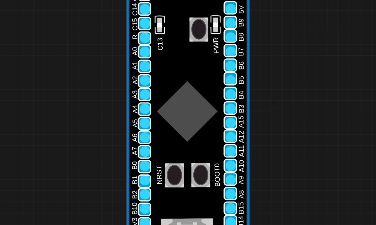
The exact circuit you get when you open this example — already wired, ready to run.
The sketch
// STM32 Black Pill (STM32F401CE) — onboard LED on PC13 (active LOW).

void setup() {
  pinMode(PC13, OUTPUT);
  Serial.begin(115200);
  Serial.println("SENSBENCH STM32 F401 Black Pill");
}

void loop() {
  digitalWrite(PC13, LOW);   // LED on
  delay(200);
  digitalWrite(PC13, HIGH);  // LED off
  delay(200);
}
How it works
pinMode(PC13, OUTPUT) configures the F401’s port C pin 13, then the loop alternates LOW (LED on) and HIGH (off) at 200 ms — a 2.5 Hz blink. The active-LOW polarity is the only real logic in the sketch; the F401’s Cortex-M4 runs it trivially fast at 84 MHz.
The Serial.println() banner in setup identifies the board at 115200 baud. Under QEMU the emulated F401 executes the same instructions with real timing, so the 200 ms delays produce a genuine 2.5 Hz rhythm — the same observable behavior as on silicon.
Before you build it for real
The F401’s PC13 LED is active-LOW — LOW lights it. The chip is 3.3 V logic with no 5 V tolerance on most pins, so 5 V peripherals need level shifting. Under QEMU the emulated chip is forgiving in ways real silicon is not: a real F401 with an unpowered or misconfigured oscillator simply never boots, while the emulator always starts. And the F401’s 64 KB RAM is a real constraint for buffer-heavy sketches — the emulator does not stop you exceeding it, but real firmware will fault.
Related examples
FAQ
How is the F401 Black Pill different from the F411 one?
The F401CE runs at 84 MHz with 256 KB flash and 64 KB RAM — roughly half the F411’s resources. Both are Cortex-M4 with FPU, both put the LED on PC13 active-LOW, and blink code is byte-for-byte identical. The F401 is the budget pick; choose the F411 when RAM or flash headroom matters.
Why does the LED logic look inverted?
On the Black Pill, the LED sits between PC13 and 3.3 V, so the pin must sink current to light it — LOW turns it on, HIGH turns it off. The sketch writes LOW with the comment “LED on”; copying this to an Arduino-style active-HIGH board makes the blink appear backwards.