
[STM32 + STM32] Blue Pill → Black Pill
[STM32 + STM32] Blue Pill → Black Pill is a runnable microcontroller simulation example on SensBench — open the wired circuit, inspect the code, and compile real firmware in your browser, no install needed. Last updated Aug 14, 2026.
FREE SIMULATOR EXAMPLE · INTERMEDIATE
[STM32 + STM32] Blue Pill → Black Pill
This example wires two different STM32 boards together: a Blue Pill (F103) toggles PA1 at 1.5 Hz, and a Black Pill (F411) reads that line on PA0 and mirrors it to its onboard LED. Two QEMU instances, one wire, and the simplest possible cross-board demo.
| Board | STM32 Blue Pill (STM32F103C8, Cortex-M3, 72 MHz) |
|---|---|
| Difficulty | intermediate |
| Category | communication |
| Libraries | None — just the Arduino core |
| Runs in | Sensbench browser simulator — free, no account |
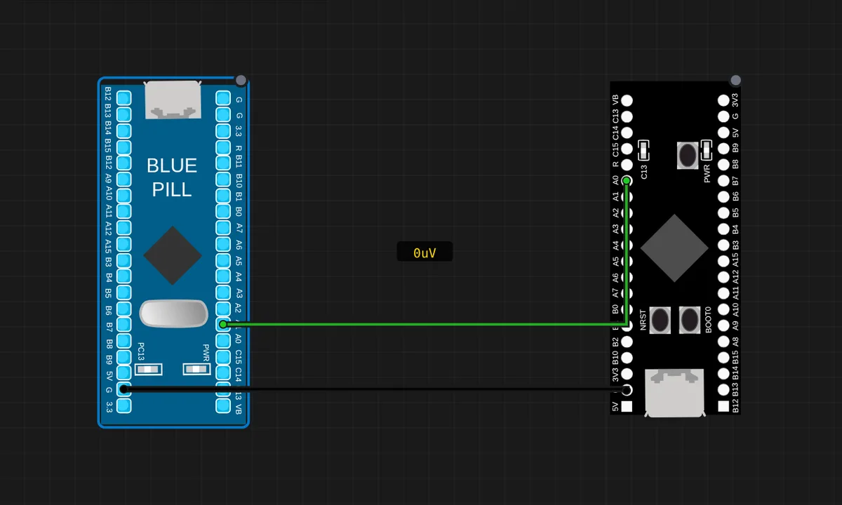
The exact circuit you get when you open this example — already wired, ready to run.
The sketch
// Blue Pill (F103) — drives PA1 at ~1.5 Hz.
// Wiring: BluePill PA1 -> BlackPill PA0,  GND -> GND.
void setup() {
  pinMode(PA1, OUTPUT);
  pinMode(PC13, OUTPUT);
  Serial.begin(115200);
}
void loop() {
  digitalWrite(PA1, HIGH); digitalWrite(PC13, LOW);
  Serial.println("PA1 HIGH"); delay(350);
  digitalWrite(PA1, LOW);  digitalWrite(PC13, HIGH);
  Serial.println("PA1 LOW");  delay(350);
}
How it works
The Blue Pill (F103) drives PA1 as a square wave at about 1.5 Hz — 350 ms HIGH, 350 ms LOW — while its own PC13 LED mirrors the state as a visual reference. The Black Pill (F411) reads PA0 on the other end and mirrors it to its onboard PC13 LED. The wire between PA1 and PA0 is the entire communication channel.
Both boards run under separate QEMU instances, so this is a genuinely heterogeneous demo: two emulated STM32s sharing a simulated wire. The Blue Pill’s Serial.println() names every transition, and the Black Pill’s LED is the receiving side’s proof — watch one board print and the other light up in agreement.
Before you build it for real
The two boards are both 3.3 V logic, so a direct wire is safe — but the moment you mix in a 5 V board, the level difference becomes a real hazard and a divider or level shifter is required. The common ground is essential: forget the GND wire and the Black Pill reads noise. On real hardware this demo also needs shared pull discipline — an input pin left floating between toggles can read garbage, though this sketch’s active drive avoids it. And both boards’ PC13 LEDs are active-LOW, so “HIGH on PA1” and “LED off” may look contradictory until you remember the polarity.
Get the parts
Related examples
FAQ
Why do both boards need a common ground?
A digital signal is a voltage referenced to ground — if the two boards do not share a ground reference, the Black Pill reads PA1’s level against its own floating ground and the signal is meaningless. The GND-to-GND wire is not optional; it is half of every signal path.
Why toggle at 1.5 Hz instead of faster?
At 350 ms per level the state changes are slow enough to watch on both boards at once — you can literally see the Blue Pill’s PA1 pin, the wire, and the Black Pill’s LED agree. Faster toggling (kHz) would still work electrically but the demo would be unwatchable.