
STM32: MPU6050 IMU (I2C)
STM32: MPU6050 IMU (I2C) is a runnable microcontroller simulation example on SensBench — open the wired circuit, inspect the code, and compile real firmware in your browser, no install needed. Last updated Aug 14, 2026.
FREE SIMULATOR EXAMPLE · INTERMEDIATE
STM32: MPU6050 IMU (I2C)
This example reads the MPU6050 6-axis IMU over the STM32 Blue Pill’s I2C1 bus (SCL=PB6, SDA=PB7): first the WHO_AM_I identity register, then the raw accelerometer X/Y/Z axes. It is a pure Wire example — no sensor library — so you see every register transaction.
| Board | STM32 Blue Pill (STM32F103C8, Cortex-M3, 72 MHz) |
|---|---|
| Difficulty | intermediate |
| Category | sensors |
| Libraries | None — just the Arduino core |
| Runs in | Sensbench browser simulator — free, no account |
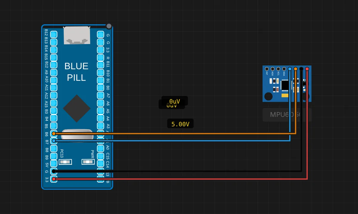
The exact circuit you get when you open this example — already wired, ready to run.
The sketch
// STM32 Blue Pill (F103) — MPU6050 6-axis IMU over I2C1
// Wiring: SDA -> PB7  |  SCL -> PB6  |  VCC -> 3V3  |  GND -> GND
#include <Wire.h>

const uint8_t MPU = 0x68;

void setup() {
  Serial.begin(115200);
  Wire.begin();              // I2C1: SCL=PB6, SDA=PB7
  // Wake the device (clear SLEEP bit in PWR_MGMT_1).
  Wire.beginTransmission(MPU); Wire.write(0x6B); Wire.write(0x00); Wire.endTransmission();
  // WHO_AM_I (0x75) should read 0x68.
  Wire.beginTransmission(MPU); Wire.write(0x75); Wire.endTransmission(false);
  Wire.requestFrom(MPU, (uint8_t)1);
  uint8_t who = Wire.read();
  Serial.print("MPU6050 WHO_AM_I = 0x"); Serial.println(who, HEX);
}

void loop() {
  // Burst-read the 6 accelerometer bytes starting at ACCEL_XOUT_H (0x3B).
  Wire.beginTransmission(MPU); Wire.write(0x3B); Wire.endTransmission(false);
  Wire.requestFrom(MPU, (uint8_t)6);
  int16_t ax = (Wire.read() << 8) | Wire.read();
  int16_t ay = (Wire.read() << 8) | Wire.read();
  int16_t az = (Wire.read() << 8) | Wire.read();
  Serial.print("AX="); Serial.print(ax);
  Serial.print("  AY="); Serial.print(ay);
  Serial.print("  AZ="); Serial.println(az);
  delay(1000);
}
How it works
The sketch wakes the MPU6050 by clearing the SLEEP bit in PWR_MGMT_1 (register 0x6B) — chips ship in sleep mode to save battery. Then it reads WHO_AM_I (0x75), which should return 0x68. Both are done with raw Wire transactions: write the register address, then requestFrom and read the response.
The loop burst-reads six bytes starting at ACCEL_XOUT_H (0x3B) and stitches each 16-bit axis from two bytes: (Wire.read() << 8) | Wire.read() — big-endian, high byte first. The three accelerometer values print once per second, and the 16-bit math shows exactly how a raw I2C register dump becomes a sensor reading.
Before you build it for real
The MPU6050 has two I2C addresses, 0x68 and 0x69, selected by the AD0 pin. This sketch hard-codes 0x68; if your module's AD0 is tied high, WHO_AM_I will never respond. The chip also wakes in sleep mode — the register write at setup is not optional, a skipped wake-up reads all-zero axes. And while this sketch reads raw counts, real projects need the scaling factor: at ±2 g default, divide by 16384 to get g. The MPU6050 is also famous for regulator noise on the 3.3 V rail — a 100 nF decoupling cap on VCC is cheap insurance on a real build.
Get the parts
Related examples
FAQ
What does WHO_AM_I prove?
The MPU6050's WHO_AM_I register (0x75) returns a fixed identity value, normally 0x68. Reading it confirms three things at once: the I2C wiring is correct, the address is right, and the chip is alive. It is the single best first read for any new I2C sensor.
Why are the accelerometer values raw 16-bit numbers?
The sketch reads the raw ADC counts straight from the sensor — at the default ±2 g full-scale range, 32768 counts maps to 2 g, so a value of 16384 means 1 g of acceleration. Converting to g or m/s² needs the configured range; the raw read keeps the example focused on the I2C mechanics.