
STM32: Stepper Motor
STM32: Stepper Motor is a runnable microcontroller simulation example on SensBench — open the wired circuit, inspect the code, and compile real firmware in your browser, no install needed. Last updated Aug 14, 2026.
FREE SIMULATOR EXAMPLE · INTERMEDIATE
STM32: Stepper Motor
This example rotates a stepper motor with the classic four-pin full-step sequence — A+, B+, A-, B- — driven directly from PA0-PA3 of the STM32 Blue Pill. It is the rawest possible stepper demo: no driver chip, no library, just four GPIOs and a state table.
| Board | STM32 Blue Pill (STM32F103C8, Cortex-M3, 72 MHz) |
|---|---|
| Difficulty | intermediate |
| Category | motors |
| Libraries | None — just the Arduino core |
| Runs in | Sensbench browser simulator — free, no account |
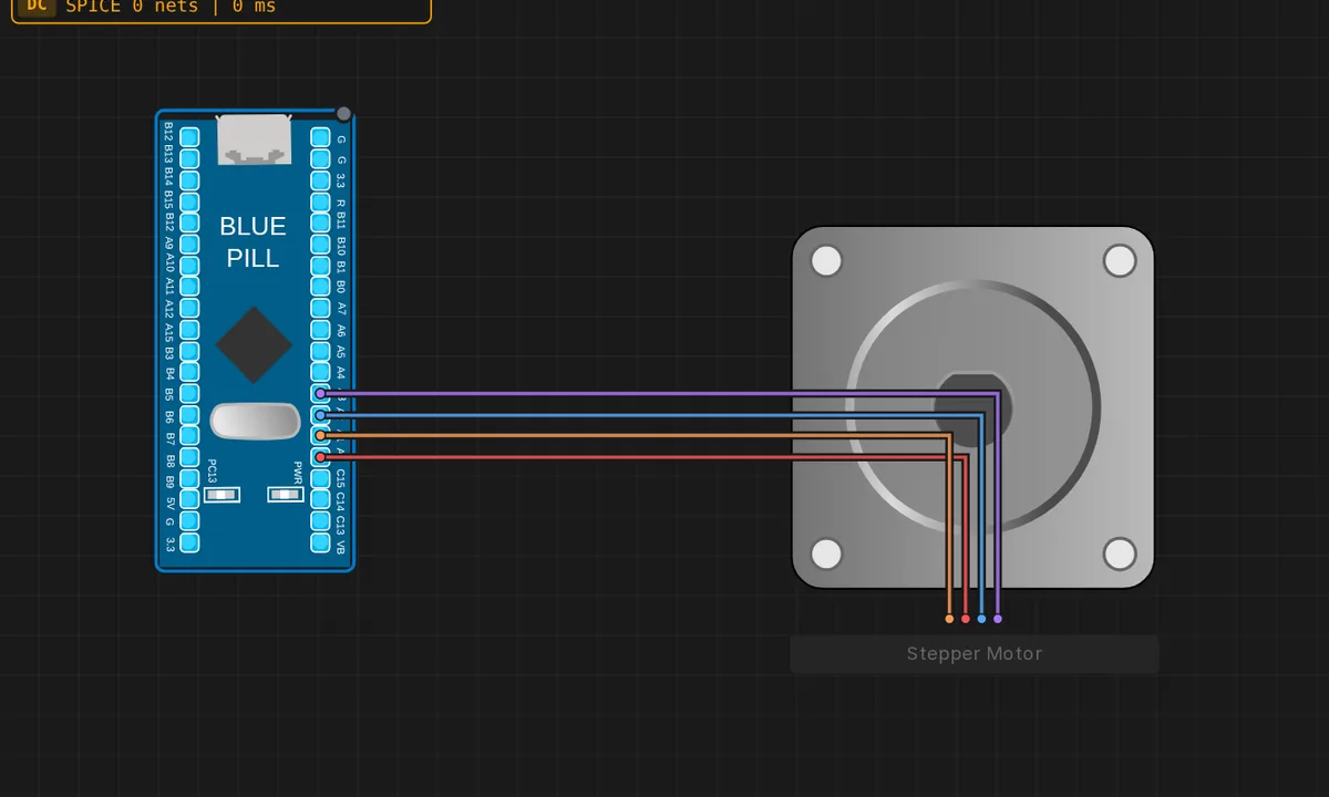
The exact circuit you get when you open this example — already wired, ready to run.
The sketch
// STM32 Blue Pill (F103) — bipolar stepper, full-step sequence
// Coils: A+ = PA0, A- = PA1, B+ = PA2, B- = PA3
const int Ap = PA0, An = PA1, Bp = PA2, Bn = PA3;

// Full-step order energizing one coil at a time: A+, B+, A-, B-
const uint8_t seq[4][4] = {
  { 1, 0, 0, 0 },   // A+
  { 0, 0, 1, 0 },   // B+
  { 0, 1, 0, 0 },   // A-
  { 0, 0, 0, 1 },   // B-
};

void setup() {
  Serial.begin(115200);
  pinMode(Ap, OUTPUT); pinMode(An, OUTPUT);
  pinMode(Bp, OUTPUT); pinMode(Bn, OUTPUT);
  Serial.println("Stepper running");
}

void loop() {
  static int s = 0;
  digitalWrite(Ap, seq[s][0]); digitalWrite(An, seq[s][1]);
  digitalWrite(Bp, seq[s][2]); digitalWrite(Bn, seq[s][3]);
  Serial.print("step "); Serial.println(s);
  s = (s + 1) % 4;
  delay(300);
}
How it works
Four pins — PA0 (A+), PA1 (A-), PA2 (B+), PA3 (B-) — are set as outputs, and a seq table holds the four full-step states: one coil energized at a time, cycling A+, B+, A-, B-. Each loop iteration writes the current row to the four pins, prints the step number, and advances to the next state with (s + 1) % 4.
The static int s keeps the step position across loop iterations — the motor’s place in the sequence survives every pass. The 300 ms delay sets the step rate: slow enough to watch each coil engage, which is the point of a teaching example; a real motor would be stepped hundreds of times faster.
Before you build it for real
Driving a motor coil directly from MCU pins only survives in a simulator. A real bipolar stepper draws hundreds of milliamps per coil — far beyond the F103’s per-pin limits — and the back-EMF from de-energized coils can exceed the supply rail and damage GPIOs. Real builds use a driver chip (A4988, DRV8825) or transistor array with a separate motor supply. Also, the full-step sequence here is one-coil-at-a-time; two-coil stepping produces higher torque at the cost of more current, and half-stepping doubles resolution. The simulator’s motor ignores torque limits entirely — real ones stall and heat up.
Get the parts
Related examples
FAQ
What is a full-step sequence?
A bipolar stepper has four coil leads: A+, A-, B+, B-. Energizing them one at a time in order — A+, B+, A-, B- — drags the rotor to four stable positions per revolution (200 steps for a 1.8-degree motor). Each step is a single seq row in the table.
Why step manually instead of using a driver chip?
Driving the coils directly shows exactly what a driver like the A4988 does internally. The trade-off: this sketch draws motor current straight from the MCU pins, which only works for tiny motors in a simulator. Real steppers need a driver with a separate power supply.