
[STM32 + Arduino] GPIO Mirror
[STM32 + Arduino] GPIO Mirror is a runnable microcontroller simulation example on SensBench — open the wired circuit, inspect the code, and compile real firmware in your browser, no install needed. Last updated Aug 14, 2026.
FREE SIMULATOR EXAMPLE · INTERMEDIATE
[STM32 + Arduino] GPIO Mirror
This example connects an STM32 Blue Pill to an Arduino Uno: the Blue Pill toggles PA1 every 500 ms, and the Uno reads that level on pin 2 and mirrors it to its built-in pin 13 LED. A QEMU ARM core and an avr8js AVR core share one simulated wire.
| Board | STM32 Blue Pill (STM32F103C8, Cortex-M3, 72 MHz) |
|---|---|
| Difficulty | intermediate |
| Category | communication |
| Libraries | None — just the Arduino core |
| Runs in | Sensbench browser simulator — free, no account |
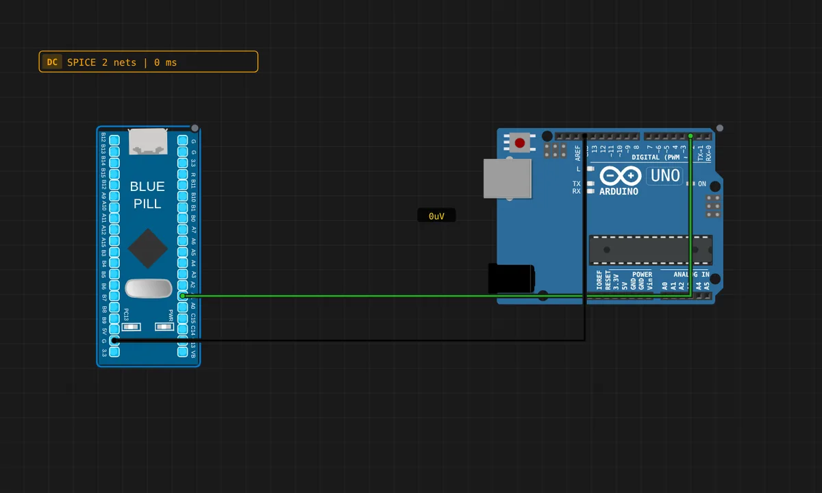
The exact circuit you get when you open this example — already wired, ready to run.
The sketch
// STM32 Blue Pill — drives PA1 as a 1 Hz square wave.
// Wiring: STM32 PA1 -> Uno pin 2,  STM32 GND -> Uno GND.
void setup() {
  pinMode(PA1, OUTPUT);
  pinMode(PC13, OUTPUT);
  Serial.begin(115200);
  Serial.println("STM32 driving PA1");
}

void loop() {
  digitalWrite(PA1, HIGH);
  digitalWrite(PC13, LOW);   // onboard LED on (active-low)
  Serial.println("PA1 -> HIGH");
  delay(500);
  digitalWrite(PA1, LOW);
  digitalWrite(PC13, HIGH);
  Serial.println("PA1 -> LOW");
  delay(500);
}
How it works
The Blue Pill drives PA1 as a 1 Hz square wave (500 ms per level). The Uno reads its pin 2 with digitalRead() and mirrors the value to the built-in LED on pin 13. The wire between STM32 PA1 and Uno pin 2 carries the signal; the two grounds are tied together.
This is a genuinely heterogeneous simulation: a QEMU STM32 driving an avr8js Arduino over a shared wire. The Blue Pill’s serial output names each transition, and the Uno’s LED is the receiver’s visual proof — the two boards stay in agreement across two completely different emulation engines.
Before you build it for real
The 3.3 V vs 5 V boundary is the whole story here. The Blue Pill’s PA1 outputs 3.3 V, which the Uno’s 5 V logic reads as a valid HIGH — but the Uno’s pin 2 pull-up is to 5 V, and when the STM32 drives LOW, current can flow back into the 3.3 V pin. On a real bench this works with many Blue Pill clones but is not guaranteed safe; a bidirectional level shifter is the honest fix. In the simulator everything is ideal, which is exactly why the pitfall is worth remembering before building. Also note both boards need a common ground — without it the signal has no reference.
Get the parts
Related examples
FAQ
Why is the Uno's LED on pin 13?
The Uno’s built-in LED is hard-wired to pin 13, the same pin as the SPI clock (SCK). It is the standard Arduino status LED, and the sketch’s digitalWrite(13, ...) mirrors whatever the STM32 sends on pin 2 — a visual one-wire protocol.
Is a direct STM32-to-Uno GPIO wire safe?
Not for the STM32. The Uno’s pin 2 is a 5 V-logic input with an internal pull-up to 5 V — driving it from the Blue Pill’s 3.3 V PA1 reads fine as HIGH on the Uno, but the pull-up can push current back into the STM32 pin. In the simulator it is safe; on a real bench use a level shifter or verify the pull-up situation.