
Voltage Divider
Voltage Divider is a runnable microcontroller simulation example on SensBench — open the wired circuit, inspect the code, and compile real firmware in your browser, no install needed. Last updated Aug 14, 2026.
FREE SIMULATOR EXAMPLE · BEGINNER
Voltage Divider
This example reads the output of a two-resistor voltage divider on the Arduino Uno’s A0 — the fundamental analog circuit behind potentiometers, photoresistors, thermistors, and most other analog sensors. Turn the resistor values and watch the voltage respond live.
| Board | Arduino Uno (ATmega328P) + analog SPICE circuit |
|---|---|
| Difficulty | beginner |
| Category | circuits |
| Libraries | None — just the Arduino core |
| Runs in | Sensbench browser simulator — free, no account |
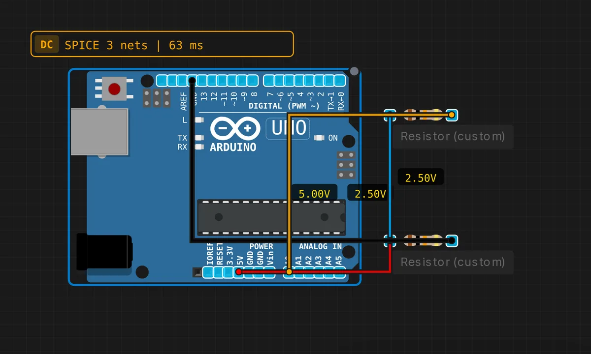
The exact circuit you get when you open this example — already wired, ready to run.
The sketch
// Voltage Divider — reads V_out = 5 * R2/(R1+R2)
void setup() { Serial.begin(9600); }
void loop() {
  int raw = analogRead(A0);
  float v = raw * 5.0 / 1023.0;
  Serial.print("V_out = "); Serial.print(v, 3); Serial.println(" V");
  delay(500);
}
How it works
Two resistors in series across 5 V divide the supply: the output at the junction is V_out = 5 × R2/(R1+R2). The sketch reads that node on A0 and converts the raw 0-1023 ADC value back to volts with raw × 5.0 / 1023.0. The formula printed in the comment is the whole lesson.
The loop prints the measured output voltage every 500 ms. Watch the value when you change R1 or R2 in the simulator — the reading updates instantly, which is the fastest way to internalize how the ratio drives the output. The ADC loading is negligible because the divider’s impedance is low (kOhm range) compared to the ADC input impedance.
Note the voltage scaling assumes exactly 5.0 V on the rail. The Uno’s USB supply is nominally 5 V but can sit a few percent off; the divider’s output scales proportionally, so a 5.2 V rail produces a 4% error in every reading.
Before you build it for real
The divider’s accuracy is limited by its resistor tolerances: two 5% resistors can produce a 10% worst-case error at the junction. The ADC reference is the 5 V rail, which is not a precision reference — USB power can sit at 4.8-5.2 V, shifting every reading. And the source impedance matters: a divider built with megohm resistors sags when the ADC samples because the ATmega328P’s sample-and-hold capacitor charges through it; the rule of thumb is keep the divider impedance below 10 kOhm.
Get the parts
Related examples
FAQ
Why is this the most important analog circuit?
Almost every analog sensor you will ever connect to a microcontroller is a voltage divider in disguise: potentiometers, photoresistors, thermistors, and many other sensors change their resistance and form a divider with a fixed resistor. If you understand the divider formula, you understand how most sensors get read.
What happens if I swap R1 and R2?
The formula V_out = 5 × R2/(R1+R2) only depends on the ratio, so swapping the two resistors inverts the output mapping — the divider still works, just the relationship between R2 and the output flips. What breaks is any calibration you did assuming the original orientation.