
Bluetooth Based Wireless LED Control System
Bluetooth Based Wireless LED Control System is a runnable microcontroller simulation example on SensBench — open the wired circuit, inspect the code, and compile real firmware in your browser, no install needed. Last updated Aug 14, 2026.
FREE SIMULATOR EXAMPLE · ADVANCED
Bluetooth Based Wireless LED Control System
This example controls an LED on the ESP32 over Bluetooth — the board appears as a classic BT serial port, and ON/OFF commands from any paired device drive the pin. Wireless UART in its simplest form.
| Board | ESP32 DevKit (Xtensa LX6, 240 MHz) |
|---|---|
| Difficulty | advanced |
| Category | communication |
| Libraries | None — just the Arduino core |
| Runs in | Sensbench browser simulator — free, no account |
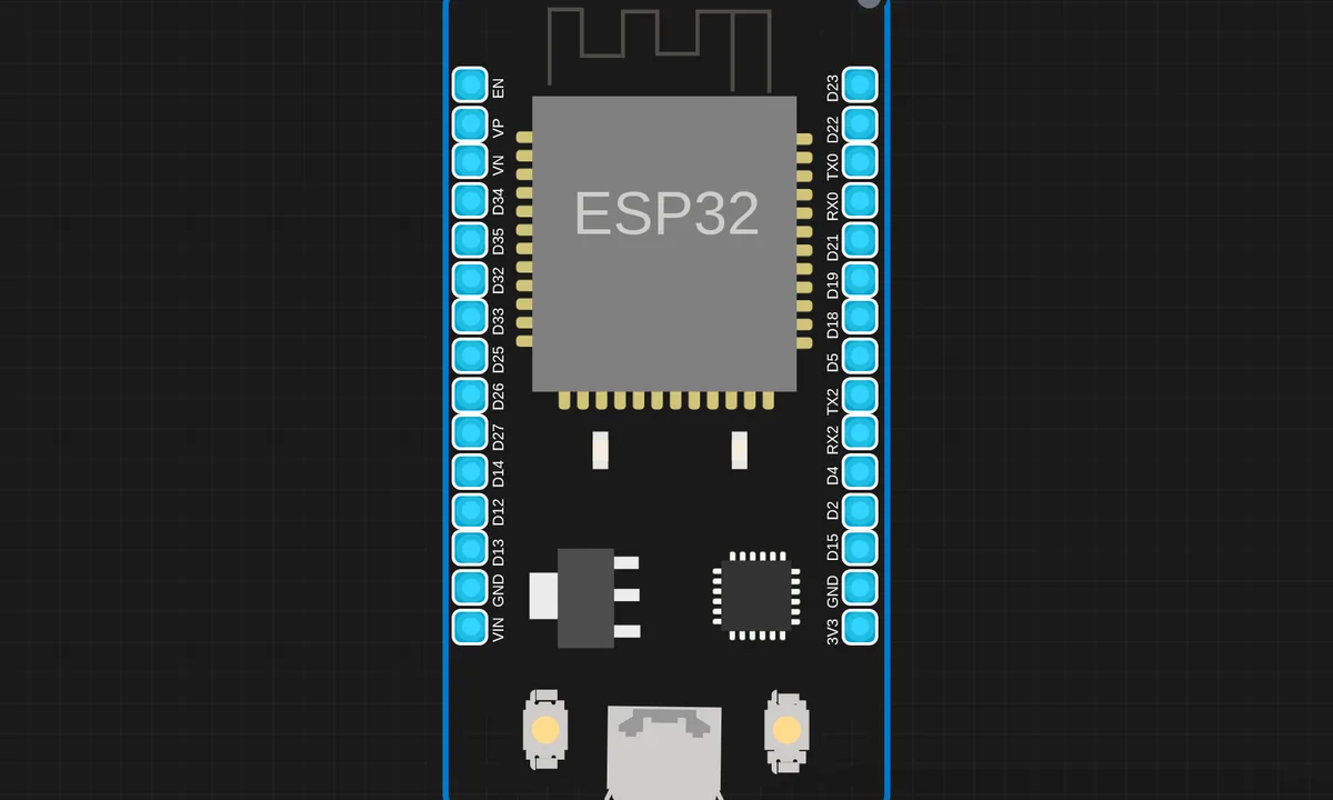
The exact circuit you get when you open this example — already wired, ready to run.
The sketch
# main.py
from machine import Pin, UART

uart = UART(0, 9600)
led = Pin("LED", Pin.OUT)

print("Bluetooth Control Ready")

while True:
    if uart.any() > 0:
        data = uart.read().decode().strip()   # decode bytes → string
        print("Received:", data)

        if "on" in data.lower():
            led.value(1)
            print("LED ON")
            uart.write("LED ON\n")

        elif "off" in data.lower():
            led.value(0)
            print("LED OFF")
            uart.write("LED OFF\n")
How it works
The ESP32 advertises a Bluetooth SPP service and listens for incoming serial data. The script parses simple commands — the canonical ON and OFF strings — and drives the LED pin accordingly. The BT stack handles pairing and connection, so the application code is just serial parsing.
The setup code initializes the classic BT module with a device name; from then on the phone sees a serial port. The loop’s read-and-act pattern is identical to wired serial, which is the point: Bluetooth SPP is wireless UART.
Before you build it for real
Classic Bluetooth SPP is 2.4 GHz and range-limited — the same band as WiFi, so coexistence matters in real deployments; the ESP32’s radio shares time between BT and WiFi, and running both degrades both. The protocol has no authentication beyond pairing: anyone paired can drive the LED, so this is a demo pattern, not a security boundary. And the LED still needs its series resistor — the simulator’s LED is free, real silicon is not.
Get the parts
Related examples
FAQ
Bluetooth Classic or BLE?
The project uses classic Bluetooth SPP (Serial Port Profile) — the ESP32 appears as a serial device, and anything that can open a serial connection can send the on/off commands. Classic BT is simpler than BLE for this use case and pairs with phones without an app.
Why serial-style commands for an LED?
Because classic Bluetooth’s natural interface is a serial stream — the same bytes a UART would carry, wirelessly. The command set (ON/OFF) is trivially small, which keeps the entire protocol to two strings.