
Intel 8080 Button Counter
Intel 8080 Button Counter is a runnable microcontroller simulation example on SensBench — open the wired circuit, inspect the code, and compile real firmware in your browser, no install needed. Last updated Aug 14, 2026.
FREE SIMULATOR EXAMPLE · INTERMEDIATE
Intel 8080 Button Counter
This example runs a self-contained Intel 8080: press INC and its 34-byte ROM program counts up in binary on 8 LEDs, press RST and it clears. CPU, RAM and program all live inside the chip component — no board, no sketch.
| Board | Programmable Z80 chip (Zilog Z80, standalone — no Arduino) |
|---|---|
| Difficulty | intermediate |
| Category | circuits |
| Libraries | None — just the Arduino core |
| Runs in | Sensbench browser simulator — free, no account |
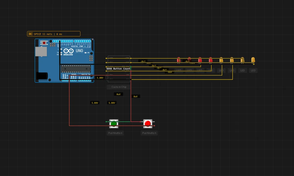
The exact circuit you get when you open this example — already wired, ready to run.
The sketch
/ Intel 8080 Button Counter — self-contained, no board.
//
// This chip runs its own embedded ROM: BTN_INC counts up in binary on the
// 8 LEDs, BTN_RST clears. There is no separate program file to edit here —
// the program lives inside the chip (double-click it, Editor tab, to view
// its C). Powered by the regulated bench supply. Click Run, then press the
// buttons.
How it works
The 8080 runs a 34-byte ROM program: BTN_INC increments a counter displayed in binary on 8 LEDs, BTN_RST clears it. The buttons are memory-mapped inputs the program polls, and the LEDs are memory-mapped outputs — the whole I/O model is port addresses, the 8080’s only I/O mechanism.
The counter visible on the LEDs is a register’s value rendered in hardware — press INC and watch bit 0 flip, then bit 1 on the next overflow. It is binary counting demonstrated by a 1974 CPU executing its own machine code, instruction by instruction.
Before you build it for real
The buttons are memory-mapped port reads — there is no debounce, so a real switch on the input port can register multiple increments per press; the emulated buttons are clean, real ones would not be. The LED bus is also port-mapped output: the chip’s 8-bit value drives 8 LEDs through the emulator’s wiring model, not through per-pin GPIO setup — the 8080 has no pinMode. And the 34-byte program is a hard budget: adding features means either shrinking code or expanding the ROM, which is the trade-off 1970s engineers lived in.
Related examples
FAQ
Where is the program if there is no sketch?
The 34-byte ROM lives inside the chip component — double-click it and open the Editor tab to see the C source. The chip is a complete system: CPU, RAM and program in one canvas component, like an EPROM-based microcomputer shrunk to a single part.
Why binary output on 8 LEDs?
Eight LEDs are eight bits — the natural output bus of an 8-bit CPU. The counter increments a register and the emulator reflects its value on the LED pins, so you are literally watching the 8080’s accumulator count in binary.