
Z80 Larson Scanner (no board)
Z80 Larson Scanner (no board) is a runnable microcontroller simulation example on SensBench — open the wired circuit, inspect the code, and compile real firmware in your browser, no install needed. Last updated Aug 14, 2026.
FREE SIMULATOR EXAMPLE · INTERMEDIATE
Z80 Larson Scanner (no board)
This example runs the classic single-bit Larson scanner on a programmable Z80 — larson.s, assembled and executed on the bare chip. No Arduino, no board: the Z80 is the whole computer.
| Board | Programmable Z80 chip (Zilog Z80, standalone — no Arduino) |
|---|---|
| Difficulty | intermediate |
| Category | circuits |
| Libraries | None — just the Arduino core |
| Runs in | Sensbench browser simulator — free, no account |
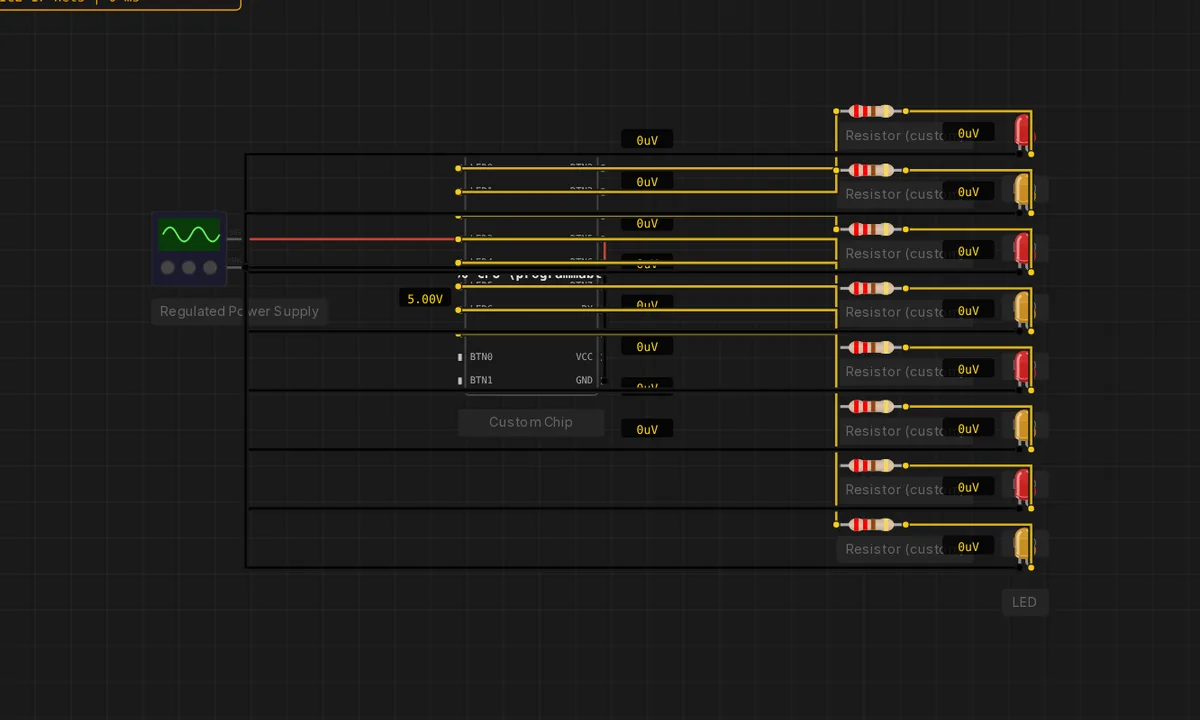
The exact circuit you get when you open this example — already wired, ready to run.
The sketch
 Larson Scanner / Knight Rider in Z80 assembly.
;
; A single LED walks left across 8 LEDs forever. Uses JR/DJNZ/RLCA --
; Z80 instructions the 8080 emulator can't run. The pattern wraps from
; bit 7 back to bit 0 thanks to RLCA's circular rotation.

        ORG 0x0000

        LD   SP, 0xBFFF        ; stack at top of RAM
        LD   A, 0x01           ; A = bit pattern (start at LED0)

loop:
        LD   (0xC000), A       ; write to LED port
        PUSH AF
        CALL delay
        POP  AF
        RLCA                   ; rotate left (bit 7 -> bit 0)
        JR   loop

; -- delay: ~80 ms outer loop -------------------------------------------
delay:
        LD   C, 80
outer:
        LD   B, 0              ; 0 = 256 inner iterations
inner:
        DJNZ inner
        DEC  C
        JR   NZ, outer
        RET
How it works
The Z80 runs larson.s — a single-bit pattern shifted across the 8-LED port, bouncing at both ends. The shift loop is the assembly-level version of the Knight-Rider pattern: load the bit, OUT it, rotate, count the delay, repeat.
Without a board, the entire circuit is the chip plus its supply and LEDs — the minimal viable Z80 computer. The assembly is assembled on run, and the LED port reflects the accumulator’s bits directly, so the sweep is the program’s inner loop made visible.
Before you build it for real
The bare-chip setup means everything the board used to provide is now your problem: power regulation, clock stability, LED current limiting — the simulator’s regulated supply hides these, real hardware does not. The program is the only thing running: no bootloader, no monitor, so a crash is total silence until reset. And the single-bit sweep’s speed is pure instruction counting — change the delay constant and the whole rhythm changes, which is tuning by feel, the 1970s way.
Related examples
FAQ
Why no board at all?
The Z80 is a complete computer on its own — CPU, program and IO need no Arduino to host them. The example strips the board away to make the point: the chip is the machine. Power, a clock, and the LED port are all the system needs.
How does this differ from the comet scanner?
The comet moves two LEDs with a tail; this is the classic single-bit Larson sweep. Both run on the same programmable Z80, but this one is the canonical pattern — one lit LED walking the bus — the version everyone recognizes.