
Dimmer LED using Potentiometer (MicroPython)
Dimmer LED using Potentiometer (MicroPython) is a runnable microcontroller simulation example on SensBench — open the wired circuit, inspect the code, and compile real firmware in your browser, no install needed. Last updated Aug 14, 2026.
FREE SIMULATOR EXAMPLE · BEGINNER
Dimmer LED using Potentiometer (MicroPython)
This example dims an LED with a potentiometer on the ESP32 — the pot feeds the ADC, the reading scales to PWM duty, and the LED brightness follows the knob. The analog-in/analog-out loop in MicroPython.
| Board | ESP32 DevKit (Xtensa LX6, 240 MHz) |
|---|---|
| Difficulty | beginner |
| Category | robotics |
| Libraries | None — just the Arduino core |
| Runs in | Sensbench browser simulator — free, no account |
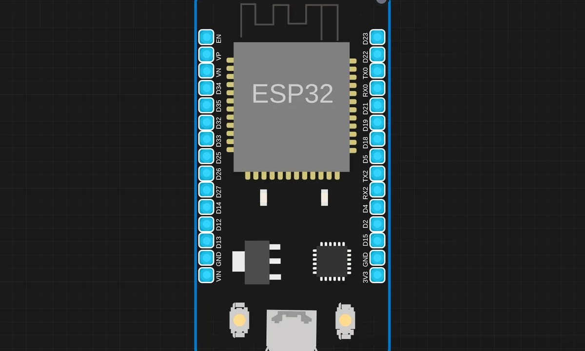
The exact circuit you get when you open this example — already wired, ready to run.
The sketch
# main.py
from machine import Pin, ADC, PWM
from time import sleep

pot = ADC(Pin(34))       # Potentiometer
pot.atten(ADC.ATTN_11DB) # 0 - 3.3V range
led = PWM(Pin(2))        # LED on GPIO2
led.freq(1000)            # 1 kHz PWM frequency

while True:
    val = pot.read()  # 0–4095 range
    duty = int((val / 4095) * 1023)  # scale to PWM duty
    led.duty(duty)
    print("ADC:", val, "→ PWM:", duty)
    sleep(0.1)
How it works
The script reads the potentiometer on the ADC and writes the scaled value to the LED’s PWM channel. Turn the knob and the duty cycle — and the brightness — follows. The mapping from 12-bit ADC to PWM resolution is the only math.
The PWM frequency sits above flicker perception, so the LED appears steady at any duty. The pot-ADC-PWM chain is the minimal analog-in to analog-out loop, the pattern every dimmer is built on.
Before you build it for real
The LED still needs its series resistor — PWM dims by switching full current on and off, so the peak current through the LED and pin is the full on-state value, not the average. The ESP32 ADC’s end-range nonlinearity compresses the knob’s extremes, and its low-bit noise makes the dimmest settings flicker slightly. And perceived brightness is nonlinear: the knob’s halfway point does not look half-bright, which is why serious dimmers map the ADC through a curve instead of a straight line.
Get the parts
Related examples
FAQ
Why PWM dimming instead of a series resistor?
A resistor sets one fixed brightness; PWM varies the duty cycle so the average current — and the perceived brightness — follows the knob continuously. The pot sets the duty, the PWM hardware switches the LED faster than the eye can follow.
Is the brightness linear with the knob?
Not exactly. LED brightness perception is roughly logarithmic, so a linear duty ramp looks brightest near the top and barely changes at the bottom. The example maps linearly for simplicity; real dimmers often apply a gamma curve.