
RGB Color Mixer using Potentiometers (ESP32 + MicroPython)
RGB Color Mixer using Potentiometers (ESP32 + MicroPython) is a runnable microcontroller simulation example on SensBench — open the wired circuit, inspect the code, and compile real firmware in your browser, no install needed. Last updated Aug 14, 2026.
FREE SIMULATOR EXAMPLE · BEGINNER
RGB Color Mixer using Potentiometers (ESP32 + MicroPython)
This example mixes RGB LED colors with three potentiometers on the ESP32 — one knob per channel, additive color in real time. The tactile color-mixer pattern in MicroPython.
| Board | ESP32 DevKit (Xtensa LX6, 240 MHz) |
|---|---|
| Difficulty | beginner |
| Category | robotics |
| Libraries | None — just the Arduino core |
| Runs in | Sensbench browser simulator — free, no account |
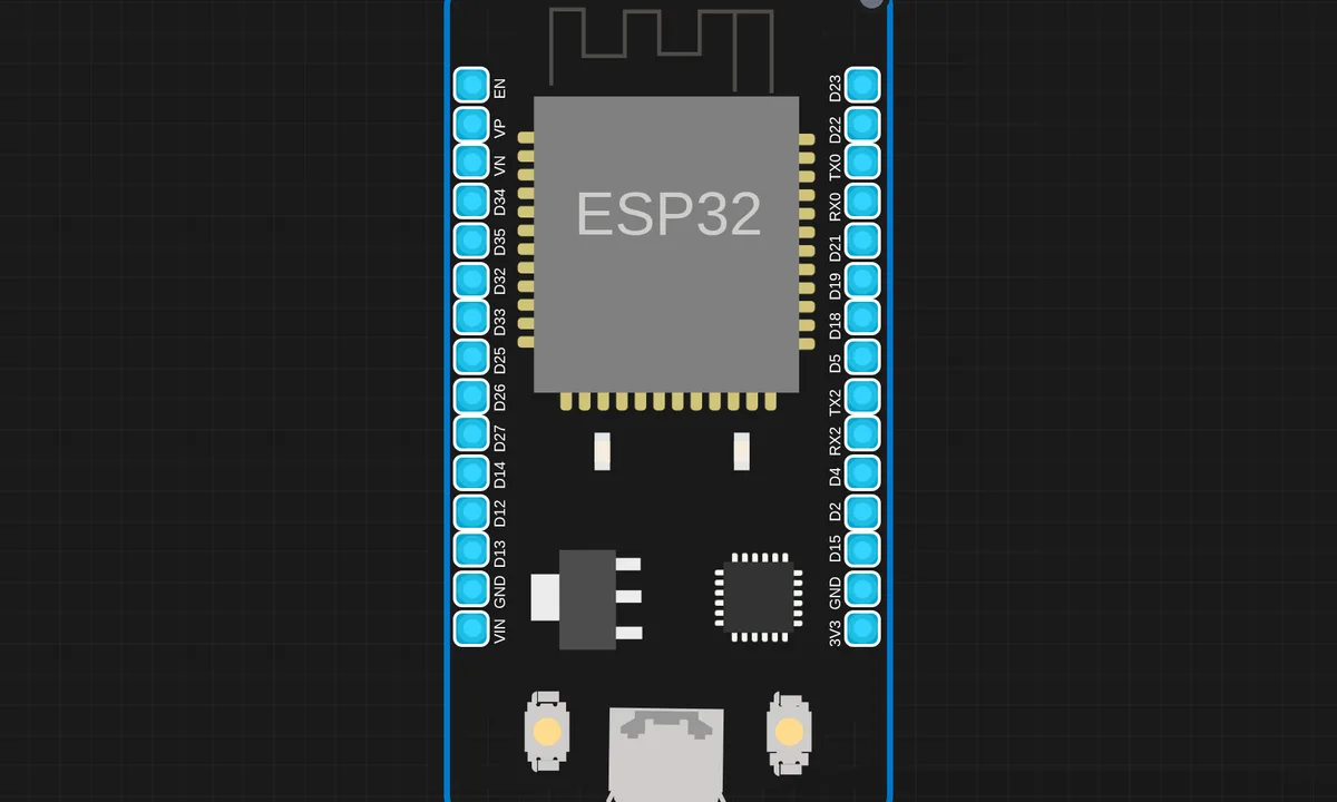
The exact circuit you get when you open this example — already wired, ready to run.
The sketch
# main.py
# ESP32 MicroPython - RGB controlled by 3 potentiometers (common-cathode example)
from machine import ADC, Pin, PWM
import time

# PWM pins for RGB
p_r = PWM(Pin(25), freq=1000)  # R
p_g = PWM(Pin(26), freq=1000)  # G
p_b = PWM(Pin(27), freq=1000)  # B

# ADC pins for pots
a_r = ADC(Pin(36))  # Pot for R
a_r.atten(ADC.ATTN_11DB)
a_g = ADC(Pin(39))
a_g.atten(ADC.ATTN_11DB)
a_b = ADC(Pin(34))
a_b.atten(ADC.ATTN_11DB)

# Helper: map ADC (0-4095) to PWM duty (0-1023)
def map_adc_to_duty(x):
    return int((x / 4095) * 1023)
# If you have common-anode LED, set invert = True
invert = False

while True:
    # Read potentiometer values
    raw_r = a_r.read()
    raw_g = a_g.read()
    raw_b = a_b.read()

    # Map to PWM duty
    r = map_adc_to_duty(raw_r)
    g = map_adc_to_duty(raw_g)
    b = map_adc_to_duty(raw_b)

    if invert:
        r = 1023 - r
        g = 1023 - g
        b = 1023 - b

    # Apply PWM
    p_r.duty(r)
    p_g.duty(g)
    p_b.duty(b)

    # Print live values
    print("ADC R: {:4d}  G: {:4d}  B: {:4d}  |  PWM R: {:4d}  G: {:4d}  B: {:4d}".format(
        raw_r, raw_g, raw_b, r, g, b
    ))

    time.sleep_ms(200)
How it works
The firmware reads three potentiometers on three ADC channels and maps each to a PWM duty on the red, green and blue pins. The RGB LED’s color is the live sum of the three knobs — turn them and the color follows in real time.
The three-channel PWM runs on the ESP32’s LEDC hardware, so the dimming is smooth and independent per channel. The mapping from ADC to PWM is the same linear scale three times, with each channel’s LED needing its own series resistor on real hardware.
Before you build it for real
Each color channel needs its own series resistor, and the values differ — red’s forward drop is lower than green and blue, so equal resistor values produce unequal brightness at full duty. The ADC end-range compression makes the knobs’ extremes less responsive than the middle, which the eye notices as a flat spot near full brightness. And perceived brightness is nonlinear — a linear knob mapping does not look linear, which is why color-accurate mixers apply a gamma curve.
Get the parts
Related examples
FAQ
Why three pots?
One per color channel: red, green and blue each get their own knob, and the LED’s color is the sum of the three levels. Three physical controls make the additive color model tangible — turn red and blue up together and the LED goes magenta.
How do the pots control brightness?
Each pot feeds an ADC channel, and the reading maps to a PWM duty on its color pin. The PWM switching is faster than the eye, so the duty becomes perceived brightness — the same dimming technique as the single-pot example, times three.