
[2× Pico W] Digital GPIO Mirror
[2× Pico W] Digital GPIO Mirror is a runnable microcontroller simulation example on SensBench — open the wired circuit, inspect the code, and compile real firmware in your browser, no install needed. Last updated Aug 14, 2026.
FREE SIMULATOR EXAMPLE · BEGINNER
[2× Pico W] Digital GPIO Mirror
This example is the simplest possible cross-board test: Pico A toggles GP15 every 500 ms, and Pico B reads that line and mirrors it to its built-in LED. One wire plus ground, and the receiving board’s LED is the proof the signal arrived.
| Board | 2× Raspberry Pi Pico (two boards, UART cross-wired) |
|---|---|
| Difficulty | beginner |
| Category | basics |
| Libraries | None — just the Arduino core |
| Runs in | Sensbench browser simulator — free, no account |
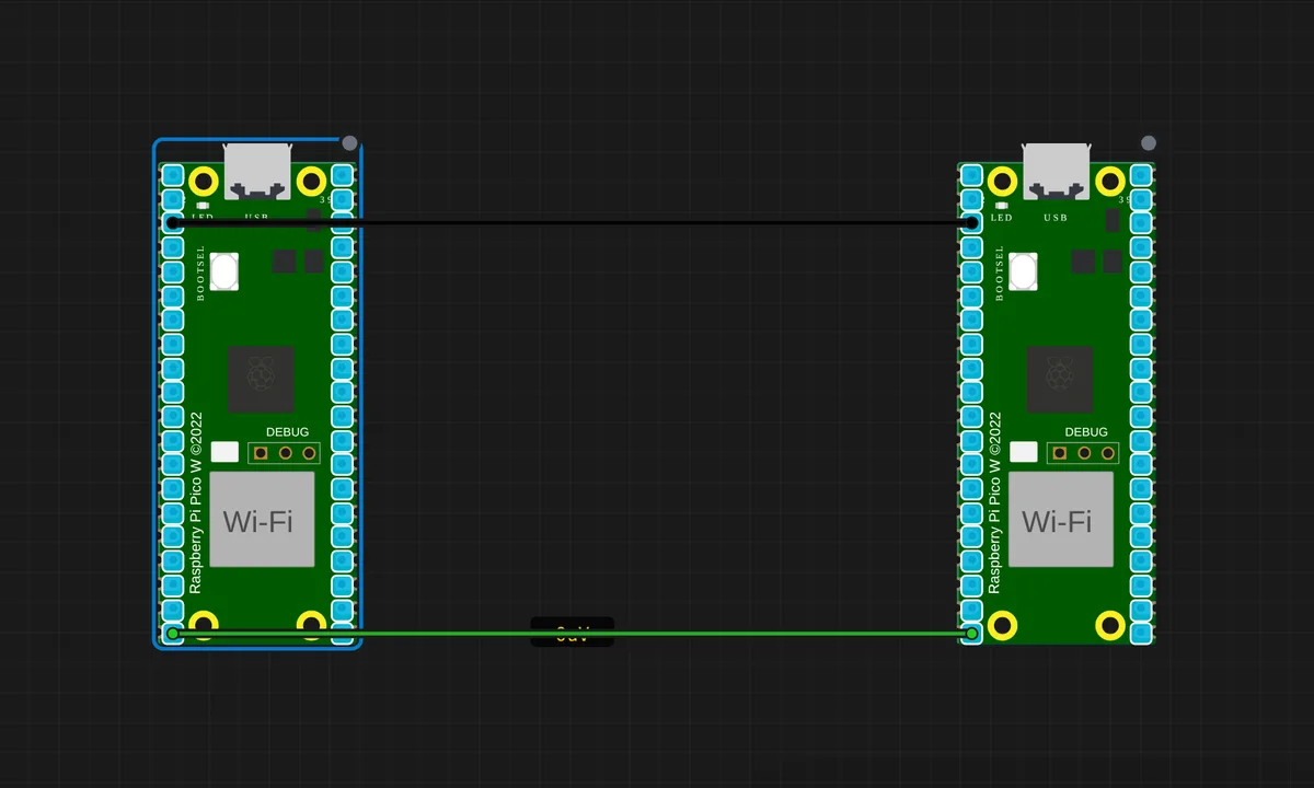
The exact circuit you get when you open this example — already wired, ready to run.
The sketch
// Pico A — Digital signal generator
// Toggles GP15 at 1 Hz (500 ms HIGH, 500 ms LOW).
//
// Wiring to Pico B:
//   A.GP15 ─── B.GP15  (signal)
//   A.GND  ─── B.GND   (common ground)

const int OUT_PIN = 15;

void setup() {
  Serial.begin(115200);
  pinMode(OUT_PIN, OUTPUT);
  pinMode(LED_BUILTIN, OUTPUT);
  delay(300);
  Serial.println("Pico A — pulse generator on GP15.");
}

void loop() {
  digitalWrite(OUT_PIN, HIGH);
  digitalWrite(LED_BUILTIN, HIGH);
  Serial.println("GP15 → HIGH");
  delay(500);

  digitalWrite(OUT_PIN, LOW);
  digitalWrite(LED_BUILTIN, LOW);
  Serial.println("GP15 → LOW");
  delay(500);
}
How it works
Pico A toggles GP15 at 1 Hz — 500 ms HIGH, 500 ms LOW — mirroring the level to its own onboard LED as a local reference and printing each transition to Serial. Pico B (companion sketch) reads GP15 as input and writes the same value to its built-in LED. Two Picos, one wire, one visible signal path.
The grounds are tied, which makes the levels meaningful — without the common ground, B has no reference to judge A’s HIGH against. Each board’s Serial Monitor prints its side of the story: A says “GP15 → HIGH”, B’s LED lights. The two consoles together are the verification: the signal made the crossing.
Before you build it for real
The single wire carries the whole signal, so the failure modes are the wire’s: a missing common ground makes the receiving Pico read noise instead of the toggling level, and a long, unshielded jumper can pick up enough interference to flip the LED spuriously. The 3.3 V levels are compatible between Picos, but if you ever bridge to a 5 V board, the 5 V output will damage the RP2040’s input. The mirror also has no debounce and no retry — if the wire blips during a transition, the LED just follows the blip, which is the point of a mirror and the reason real protocols add acknowledgment.
Get the parts
Related examples
FAQ
Why is this called a mirror?
Pico B does no logic — it just reflects whatever it sees: the input level on GP15 is copied straight to its built-in LED. The wire’s state becomes visible as a light on the receiving board. It is the simplest possible cross-board test: if the mirror works, the wire works.
Why GP15 on both boards?
GP15 is arbitrary but convenient: it is a plain, easily-reachable GPIO on both boards, and using the same number on each side avoids the “which pin did I mean?” confusion of mismatched labels. The wire is A.GP15 to B.GP15, one jumper.