
ESP32 Blink LED
FREE SIMULATOR EXAMPLE · BEGINNER
ESP32 Blink LED
This example blinks two LEDs at once: the blue built-in LED on GPIO2 of the ESP32 DevKit and an external red LED wired to GPIO4. It is the fastest way to prove the whole toolchain — code, emulation, wiring — actually works. Open it, press play, and both LEDs toggle every 500 ms while the Serial Monitor prints the state.
| Board | ESP32 DevKit (Xtensa LX6, 240 MHz) |
|---|---|
| Difficulty | beginner |
| Category | basics |
| Libraries | None — just the Arduino core |
| Runs in | Sensbench browser simulator — free, no account |
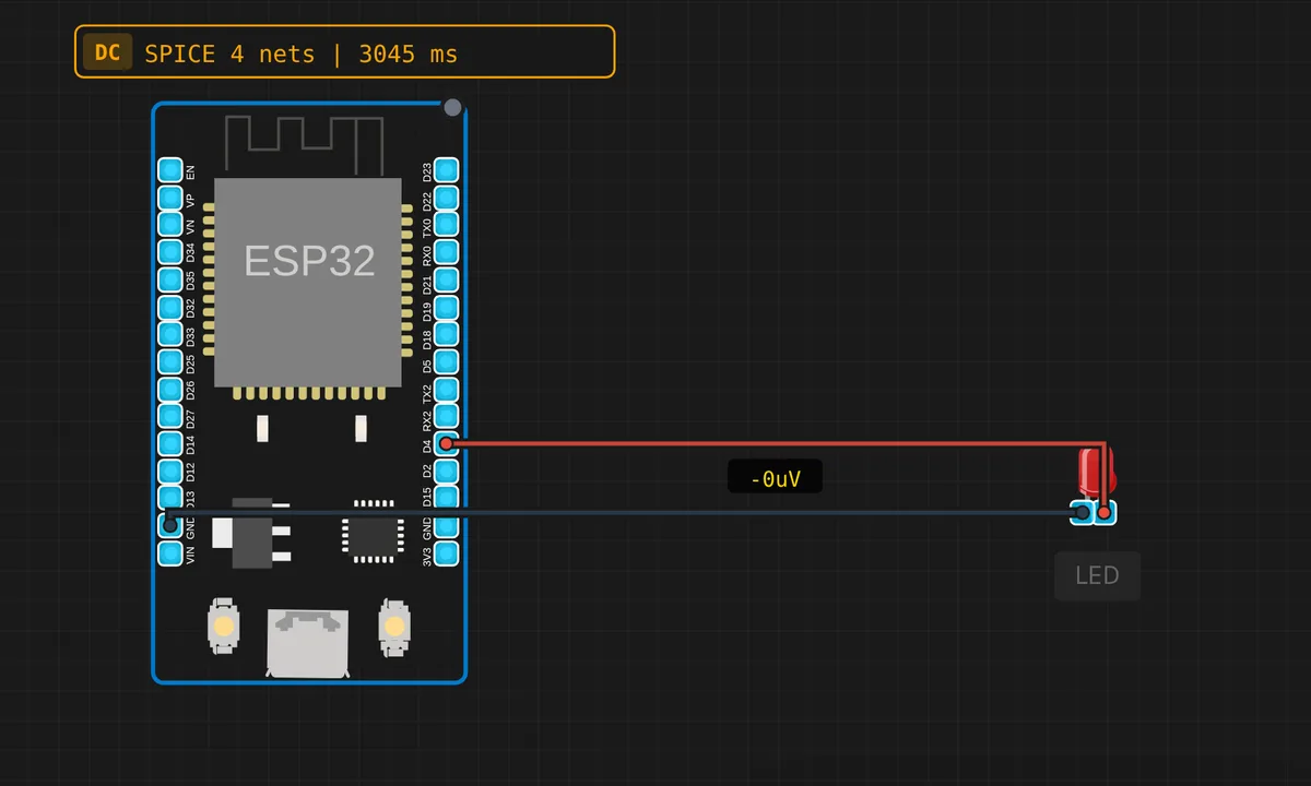
The exact circuit you get when you open this example — already wired, ready to run.
The sketch
// ESP32 Blink LED
// Blinks the built-in LED (GPIO2) and an external LED (GPIO4)
// Requires arduino-esp32 2.0.17 (IDF 4.4.x)


#define LED_BUILTIN_PIN 2   // Built-in blue LED on ESP32 DevKit
#define LED_EXT_PIN     4   // External red LED


void setup() {
  Serial.begin(115200);
  pinMode(LED_BUILTIN_PIN, OUTPUT);
  pinMode(LED_EXT_PIN, OUTPUT);
  Serial.println("ESP32 Blink ready!");
}

void loop() {
  digitalWrite(LED_BUILTIN_PIN, HIGH);
  digitalWrite(LED_EXT_PIN, HIGH);
  Serial.println("LED ON");
  delay(500);

  digitalWrite(LED_BUILTIN_PIN, LOW);
  digitalWrite(LED_EXT_PIN, LOW);
  Serial.println("LED OFF");
  delay(500);
}
How it works
The sketch configures both pins as outputs in setup(), then the loop does the simplest useful thing in embedded: write both pins HIGH, wait half a second, write both LOW, repeat. A Serial.println() on every transition means you can watch the rhythm in the Serial Monitor without even looking at the board.
GPIO2 drives the DevKit’s onboard blue LED — handy because it needs zero wiring. GPIO4 drives the external red LED you can see on the canvas. If you edit the delay values, the two stay in sync because they share the same loop: one delay(500) gates both.
Before you build it for real
Two things the simulator forgives and real silicon does not. First, the external LED in this circuit has no series resistor — fine in a simulation, but on a real board a bare red LED on a GPIO drops ~2 V against the pin’s 3.3 V and the difference burns through the pin’s current budget. Use 220 Ω in series. Second, GPIO2 is a strapping pin: it must read HIGH at boot or the ESP32 enters the wrong flash mode. An LED is fine; anything that pulls it low will stop your board from booting and the error message will not tell you why.
Get the parts
Related examples
FAQ
Which GPIO is the built-in LED on?
On most ESP32 DevKit boards it is GPIO2 — that is what this sketch uses. Some clones put it on GPIO5 instead; if your real board does not blink, try 5.
Why blink two LEDs instead of one?
The built-in LED proves the code runs. The external LED proves your wiring works. Together they separate “firmware problem” from “breadboard problem” — a distinction that matters a lot more on real hardware.