
KY-040 Rotary Encoder
KY-040 Rotary Encoder is a runnable microcontroller simulation example on SensBench — open the wired circuit, inspect the code, and compile real firmware in your browser, no install needed. Last updated Aug 14, 2026.
FREE SIMULATOR EXAMPLE · BEGINNER
KY-040 Rotary Encoder
This example reads a KY-040 rotary encoder on an Arduino Uno: turn the knob and a counter climbs or falls in the Serial Monitor, press the shaft and it snaps back to zero. CLK sits on pin 2, DT on pin 3, the push switch on pin 4, and every detent prints a fresh position line at 115200 baud.
| Board | Arduino Uno (ATmega328P, 16 MHz, 5 V logic) |
|---|---|
| Difficulty | beginner |
| Category | basics |
| Libraries | None — just the Arduino core |
| Runs in | Sensbench browser simulator — free, no account |
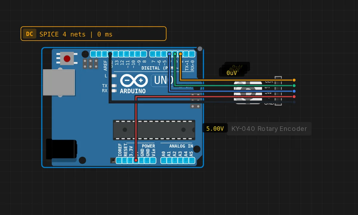
The exact circuit you get when you open this example — already wired, ready to run.
The sketch
// KY-040 rotary encoder — turn the knob to move the counter,
// press the shaft (SW) to reset. The encoder drives CLK/DT in quadrature;
// we sample DT on each CLK rising edge to get the direction.
const int PIN_CLK = 2;   // CLK (A)
const int PIN_DT  = 3;   // DT  (B)
const int PIN_SW  = 4;   // SW  (push button, active LOW)

int counter = 0;
int lastClk = HIGH;

void setup() {
  pinMode(PIN_CLK, INPUT_PULLUP);
  pinMode(PIN_DT, INPUT_PULLUP);
  pinMode(PIN_SW, INPUT_PULLUP);
  Serial.begin(115200);
  Serial.println("KY-040 rotary encoder ready");
  lastClk = digitalRead(PIN_CLK);
}

void loop() {
  int clk = digitalRead(PIN_CLK);
  if (clk != lastClk && clk == HIGH) {      // CLK rising edge
    if (digitalRead(PIN_DT) == LOW) {
      counter++;                            // DT LOW  -> clockwise
    } else {
      counter--;                            // DT HIGH -> counter-clockwise
    }
    Serial.print("position: ");
    Serial.println(counter);
  }
  lastClk = clk;

  if (digitalRead(PIN_SW) == LOW) {
    counter = 0;
    Serial.println("button pressed -> reset");
    delay(200);                             // simple debounce
  }
}
How it works
A rotary encoder outputs two square waves 90 degrees out of phase on CLK and DT — quadrature. The sketch decodes it the polling-simple way: on every rising edge of CLK (clk != lastClk && clk == HIGH) it samples DT once. DT LOW means clockwise, DT HIGH means counter-clockwise. That is coarser than a full 4x quadrature decoder, but a KY-040 detent produces exactly one CLK cycle, so one detent lands as one count.
All three inputs use INPUT_PULLUP, so the encoder’s open contacts just pull each line to ground — no external resistors needed for the switch contacts. The pin choice is also not random: pins 2 and 3 are the Uno’s only external-interrupt pins (INT0 and INT1), which means this exact wiring survives an upgrade to an attachInterrupt() version later.
The push button is active LOW: when digitalRead(PIN_SW) returns LOW the sketch zeroes the counter and burns 200 ms in delay() as a cheap debounce. If your counter counts backwards on a real build, nothing is broken — your module’s CLK and DT are simply wired the other way round relative to the sketch’s assumption, so swap the wires or flip the comparison.
Before you build it for real
Real KY-040s bounce — mechanical contacts can produce several CLK edges per detent, so a bare polling loop like this occasionally double-counts on hardware the simulator never will. Most KY-040 modules already solder 10k pull-ups on the board (the sketch’s INPUT_PULLUP covers a bare encoder), and the robust fix is moving CLK to an interrupt on pin 2 with a proper state-table decoder. Second trap: the 200 ms delay() after a button press blocks the whole loop — turn the knob during that window and those detents are silently lost. The simulator’s encoder is bounceless and patient; real ones are neither.
Get the parts
Related examples
FAQ
The counter jumps by two, or counts the wrong way — why?
Wrong direction means CLK and DT are swapped relative to what the sketch assumes: swap the two wires, or flip the == LOW comparison. Double counts are contact bounce — the simulated encoder is ideal, a real KY-040 detent can throw several CLK edges. Add debounce capacitors or move to an interrupt-driven state table on pin 2.
Does the KY-040 need 3.3 V or 5 V?
It is happy at either, which makes it one of the few modules that pairs with the Uno’s 5 V logic natively — no level shifter. Feed it 5 V on an Uno. On a 3.3 V board, power it from 3.3 V instead so its outputs never overdrive the input pins.