
LED with Current-Limiting Resistor
LED with Current-Limiting Resistor is a runnable microcontroller simulation example on SensBench — open the wired circuit, inspect the code, and compile real firmware in your browser, no install needed. Last updated Aug 14, 2026.
FREE SIMULATOR EXAMPLE · BEGINNER
LED with Current-Limiting Resistor
This example blinks an LED through a 300 ohm current-limiting resistor on the Arduino Uno’s pin 13 — the most repeated circuit in electronics, with the design math in the comments. It exists to teach why the resistor is not optional.
| Board | Arduino Uno (ATmega328P) + analog SPICE circuit |
|---|---|
| Difficulty | beginner |
| Category | circuits |
| Libraries | None — just the Arduino core |
| Runs in | Sensbench browser simulator — free, no account |
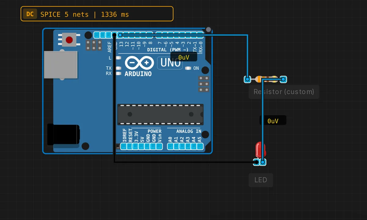
The exact circuit you get when you open this example — already wired, ready to run.
The sketch
// LED with current-limiting resistor
// R = (5V - 2V) / 10mA = 300 ohm
void setup() { pinMode(13, OUTPUT); }
void loop() {
  digitalWrite(13, HIGH); delay(1000);
  digitalWrite(13, LOW);  delay(1000);
}
How it works
The circuit is the most repeated thing in electronics: 5 V rail, a resistor, an LED, ground. The resistor sets the current via Ohm’s law — the LED’s forward drop (~2 V for red) is subtracted from the supply, and the remainder divided by the resistor gives the current.
The sketch is a plain blink on pin 13 — the circuit, not the code, is the lesson. The comment carries the design math: at 5 V supply, 2 V LED drop, and a 300 ohm resistor, the current lands at 10 mA. Change the LED color (blue needs ~3 V) and the same resistor yields less current — hence lower brightness, not danger.
The simulator shows the LED glowing at the calculated brightness. Because simulation models the forward drop and resistor, the current really is ~10 mA — but the emulator will also happily light an LED with no resistor at all, which real silicon will not survive.
Before you build it for real
The simulator’s LED needs no resistor and will never burn out — real silicon is merciless: a bare LED on 5 V pulls 30-60 mA, past the LED’s ~20 mA rating and dangerously close to the ATmega328P’s 40 mA absolute maximum per pin. The resistor value depends on the LED color: red needs ~300 ohm at 5 V, but blue and white LEDs drop ~3 V and want ~200 ohm for the same current. And the 200 mA total across all pins budget is a second ceiling: many LEDs on many pins add up fast.
Get the parts
Related examples
FAQ
Why exactly 300 ohm?
The comment shows the math: R = (5V - 2V) / 10mA = 300 ohm. The LED drops about 2 V (red LEDs are ~1.8-2.2 V), leaving 3 V across the resistor at the target 10 mA. Real projects use the nearest standard value — 330 ohm — which still lands close to 10 mA.
What happens without the resistor?
The LED’s forward drop is roughly constant, so without a resistor the current is limited only by the wiring and the pin driver — typically 30-60 mA for a bare LED at 5 V. That exceeds both the LED’s continuous rating (~20 mA) and the ATmega328P’s 40 mA absolute maximum, so either the LED or the pin fails.