
MOSFET PWM LED Dimmer
MOSFET PWM LED Dimmer is a runnable microcontroller simulation example on SensBench — open the wired circuit, inspect the code, and compile real firmware in your browser, no install needed. Last updated Aug 14, 2026.
FREE SIMULATOR EXAMPLE · INTERMEDIATE
MOSFET PWM LED Dimmer
This example dims an LED smoothly with PWM through a 2N7000 N-channel MOSFET on the Arduino Uno — pin 9’s PWM drives the gate, and the MOSFET switches the LED current. The voltage-driven gate makes this the standard low-side dimmer for power LEDs.
| Board | Arduino Uno (ATmega328P) + analog SPICE circuit |
|---|---|
| Difficulty | intermediate |
| Category | circuits |
| Libraries | None — just the Arduino core |
| Runs in | Sensbench browser simulator — free, no account |
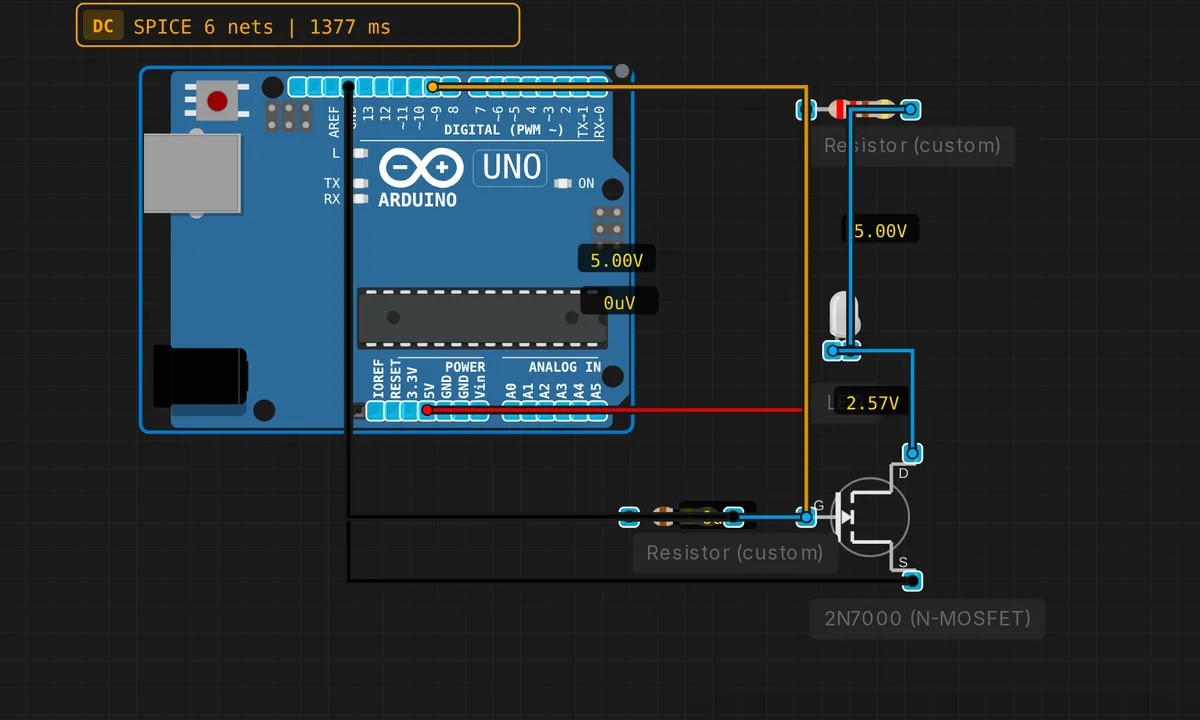
The exact circuit you get when you open this example — already wired, ready to run.
The sketch
// MOSFET PWM LED dimmer
void setup() { pinMode(9, OUTPUT); }
void loop() {
  for(int b=0; b<=255; b+=5) { analogWrite(9, b); delay(30); }
  for(int b=255; b>=0; b-=5) { analogWrite(9, b); delay(30); }
}
How it works
The 2N7000 is an N-channel MOSFET with the source grounded, the drain switching the LED, and the gate driven by pin 9. analogWrite(9, b) puts a PWM square wave on the gate, and the MOSFET switches the LED current at the same rate. Because the gate is capacitive, the pin only moves charge — the LED current comes entirely from the supply through the drain.
The loop fades the brightness in 5-unit steps — 0 to 255 and back — with 30 ms per step, a complete fade cycle of about 3 seconds. The analogWrite() duty cycle maps linearly to perceived brightness for an LED over most of the range, so the fade looks smooth.
The gate resistor (1 kOhm, typical in the wiring) damps the inrush into the gate capacitance, keeping the MCU pin within its current limits during switching edges.
Before you build it for real
A MOSFET’s gate is a capacitor, and PWM means charging it ~490 times per second — without the gate resistor, the instantaneous charge current can spike past the pin’s 40 mA limit. The gate threshold matters: the 2N7000 needs ~2-3 V to turn on fully, fine from 5 V logic, but marginal when driven from 3.3 V — the Rds rises and the MOSFET heats. And the LED still needs its series resistor on the drain side: the MOSFET limits current like a switch, not like a resistor, so the LED current is set by the resistor value, not the transistor.
Get the parts
Related examples
FAQ
Why a MOSFET instead of a bipolar transistor?
The MOSFET’s gate draws essentially zero DC current — it is voltage-driven, not current-driven. That makes it perfect for PWM: the gate capacitance charges and discharges each cycle with tiny losses, and the switching is fast and clean. Bipolars need continuous base current proportional to load current.
Why is the PWM dimming invisible as a blink?
PWM switches the LED hundreds of times per second — far faster than the eye can follow. The eye averages the on/off train into a perceived brightness proportional to duty cycle. The 2N7000 faithfully mirrors the gate’s PWM onto the LED, which is exactly what a dimmer needs.