
LED Bar Graph
LED Bar Graph is a runnable microcontroller simulation example on SensBench — open the wired circuit, inspect the code, and compile real firmware in your browser, no install needed. Last updated Aug 14, 2026.
FREE SIMULATOR EXAMPLE · BEGINNER
LED Bar Graph
This example chases a five-LED bar graph on the Arduino Uno — pins 2 through 6, each LED with its own resistor. It is the display half of a bar-graph meter: add an ADC value and the chase becomes a level indicator.
| Board | Arduino Uno (ATmega328P) + analog SPICE circuit |
|---|---|
| Difficulty | beginner |
| Category | circuits |
| Libraries | None — just the Arduino core |
| Runs in | Sensbench browser simulator — free, no account |
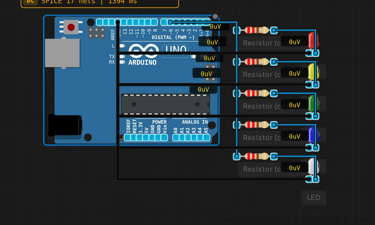
The exact circuit you get when you open this example — already wired, ready to run.
The sketch
// LED Bar Graph — 5 LEDs on pins 2-6
void setup() { for(int i=2;i<=6;i++) pinMode(i,OUTPUT); }
void loop() {
  for(int i=2;i<=6;i++) { digitalWrite(i,HIGH); delay(200); }
  for(int i=6;i>=2;i--) { digitalWrite(i,LOW);  delay(200); }
}
How it works
Five pins (2-6) are configured as outputs in a loop, and each drives its own LED through its own resistor. The forward pass lights them one at a time from 2 to 6 with 200 ms per step, and the reverse pass darkens them from 6 back to 2 — a chase that exercises every channel.
The for loops use the pin numbers directly as loop variables — a compact idiom that works because the pins are consecutive. The 200 ms step is slow enough to see each LED individually light, fast enough to read as motion.
Before you build it for real
Five LEDs at ~10 mA each is 50 mA total — over the ATmega328P’s 200 mA whole-chip budget only when other peripherals pile on, but close enough that you should count currents. Each LED needs its own resistor (220-330 ohm); a shared resistor causes uneven brightness because LED forward voltages vary. And the loop is purely blocking: delay() between steps means the Arduino cannot read sensors while chasing — a real bargraph meter would restructure this with millis()-based stepping to keep the ADC live.
Get the parts
Related examples
FAQ
Why does each LED need its own resistor?
LEDs do not share current nicely: if two LEDs with slightly different forward voltages share one resistor, the lower-voltage LED hogs the current and the other barely lights. One resistor per LED keeps each channel at its own current — the difference is small but real, and it compounds across five channels.
Why chase the LEDs instead of showing a level?
This example is the display side only — the chase pattern proves all five channels work. The natural upgrade is the bargraph mode: map a sensor value (ADC, pot, temperature) to how many LEDs light, then light LED 2..n from the bottom. The wiring stays identical; only the loop logic changes.