
NTC Temperature Sensor
NTC Temperature Sensor is a runnable microcontroller simulation example on SensBench — open the wired circuit, inspect the code, and compile real firmware in your browser, no install needed. Last updated Aug 14, 2026.
FREE SIMULATOR EXAMPLE · BEGINNER
NTC Temperature Sensor
This example reads temperature from an NTC thermistor breakout module on the Arduino Uno’s A0 — the module’s built-in 10 kOhm pull-up means only three wires to connect. The sketch converts resistance to Celsius with the beta model and prints it every second.
| Board | Arduino Uno (ATmega328P) + analog SPICE circuit |
|---|---|
| Difficulty | beginner |
| Category | circuits |
| Libraries | None — just the Arduino core |
| Runs in | Sensbench browser simulator — free, no account |
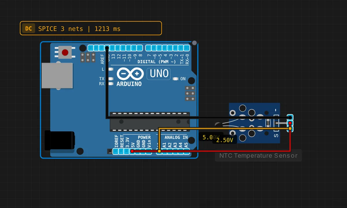
The exact circuit you get when you open this example — already wired, ready to run.
The sketch
// NTC Temperature Sensor (beta model)
#define NTC_PIN A0
#define R_PULL 10000.0
#define NTC_R0 10000.0
#define NTC_T0 298.15
#define NTC_BETA 3950.0

void setup() { Serial.begin(9600); }
void loop() {
  int raw = analogRead(NTC_PIN);
  float v = raw * 5.0 / 1023.0;
  float rNtc = R_PULL * v / (5.0 - v);
  float tK = 1.0 / (1.0/NTC_T0 + log(rNtc/NTC_R0)/NTC_BETA);
  float tC = tK - 273.15;
  Serial.print("Temp = "); Serial.print(tC, 1); Serial.println(" C");
  delay(1000);
}
How it works
The module contains a 10 kOhm pull-up to 5 V and the NTC to ground, forming a divider on A0. The sketch reads the raw value, computes the voltage, and solves for the thermistor resistance: rNtc = R_PULL × v / (5.0 - v).
The resistance is converted to Kelvin with the beta model — 1/T = 1/T0 + ln(R/R0)/B — then to Celsius. The constants at the top (R_PULL, R0, T0, BETA) are the only calibration knobs: change them for a different thermistor or pull-up, and the math follows. The 1-second loop cadence suits a slow thermal sensor.
Before you build it for real
The module’s pull-up resistor is usually a 5% part, and the NTC’s B coefficient is a datasheet nominal — together they set the accuracy ceiling at about ±1-2 °C across the range, worse near the extremes. The sketch assumes the module is on a 5 V divider; the Pico and ESP32 versions of the same module often ship with 3.3 V in mind, and mixing references shifts every reading. NTCs also self-heat: the divider current through the thermistor warms it slightly, and a 5 V supply makes that worse than 3.3 V. And this module responds slowly — the reading takes seconds to settle after a temperature step.
Get the parts
Related examples
FAQ
Why is this example different from the ATtiny85 and Pico NTC examples?
This one uses an NTC breakout module — the board already contains the 10 kOhm pull-up resistor, so the wiring is VCC, GND, and signal. The bare-thermistor versions wire their own divider. The math is identical; the module just removes the breadboard work and the tolerance guesswork.
What is the beta model?
It is the two-parameter approximation of the Steinhart-Hart equation: 1/T = 1/T0 + ln(R/R0)/B. The B coefficient (3950 here) describes how steeply the thermistor’s resistance falls with temperature. Real thermistors deviate slightly from the model, giving typically ±1 °C accuracy over the mid-range — fine for most hobby sensing.