
Comparator with LED
Comparator with LED is a runnable microcontroller simulation example on SensBench — open the wired circuit, inspect the code, and compile real firmware in your browser, no install needed. Last updated Aug 14, 2026.
FREE SIMULATOR EXAMPLE · INTERMEDIATE
Comparator with LED
This example runs an op-amp comparator on the Arduino Uno: a potentiometer on one input, a 2.5 V reference on the other, and an LED that lights when the pot wins. Turn the knob through the threshold and watch the decision flip.
| Board | Arduino Uno (ATmega328P) + analog SPICE circuit |
|---|---|
| Difficulty | intermediate |
| Category | circuits |
| Libraries | None — just the Arduino core |
| Runs in | Sensbench browser simulator — free, no account |
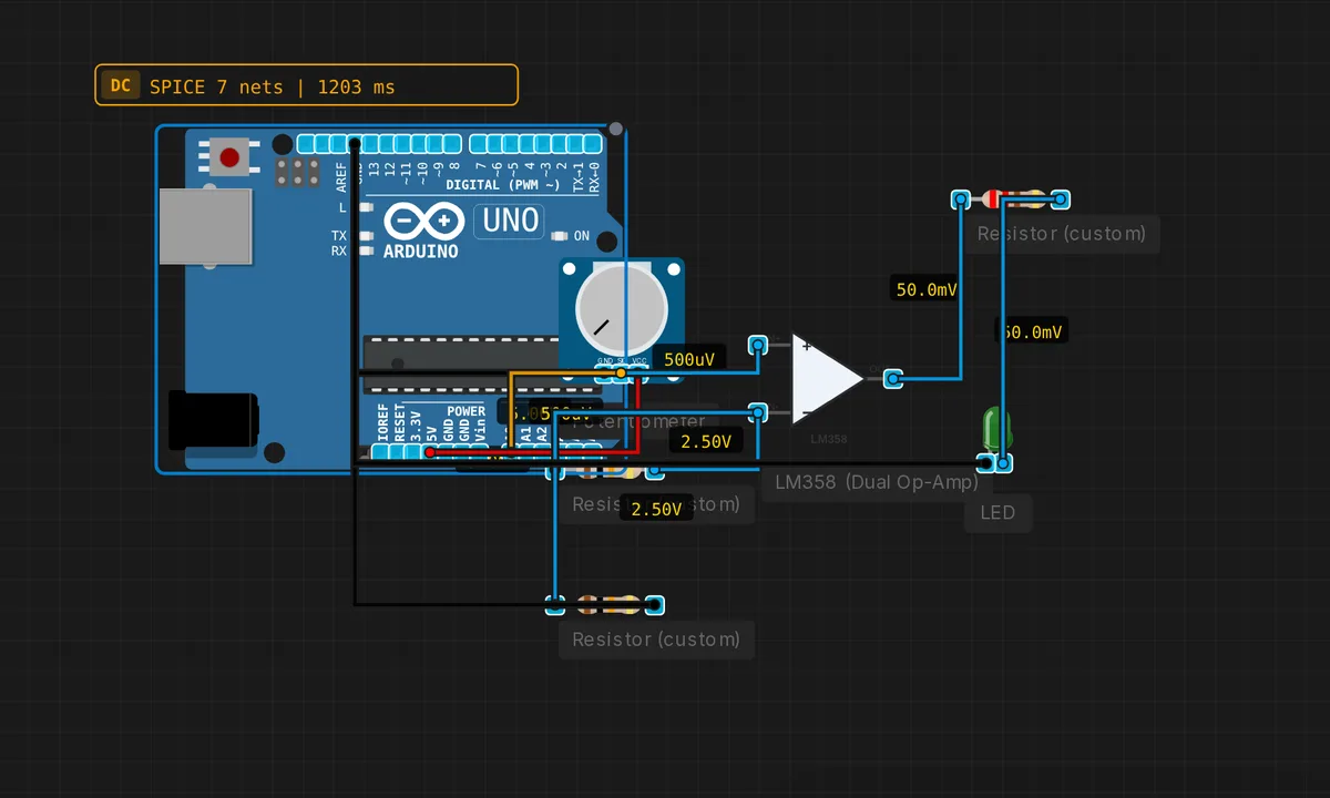
The exact circuit you get when you open this example — already wired, ready to run.
The sketch
// Comparator — LED lights when pot > 2.5V
void setup() { Serial.begin(9600); }
void loop() {
  float vpot = analogRead(A0) * 5.0 / 1023.0;
  Serial.print("Pot = "); Serial.print(vpot,2);
  Serial.println(vpot > 2.5 ? " > ref -> LED ON" : " < ref -> LED OFF");
  delay(300);
}
How it works
The op-amp compares the potentiometer voltage (non-inverting input) against the 2.5 V divider reference (inverting input). Above 2.5 V, the output goes high and the LED lights; below, it goes dark. The sketch reads the pot on A0 and prints both the voltage and the comparator’s decision — the serial line names which side of the threshold the knob is on.
The 300 ms polling makes the LED and the serial printout respond together as you drag the pot through the threshold. Crossing 2.5 V flips the LED, and the serial line flips from “< ref" to "> ref” at the same moment — the comparison made visible on two channels at once.
Before you build it for real
An open-loop comparator is exquisitely sensitive near the threshold: noise of a few millivolts around 2.5 V makes the LED chatter, flickering rapidly instead of flipping cleanly. Real comparator designs add hysteresis (positive feedback) to tame exactly this — the Schmitt trigger example in this collection is the fix. The 2.5 V divider reference is only as accurate as the rail: USB power at 4.8 V shifts the threshold to 2.4 V. And a general-purpose op-amp like the LM358 swings to its rails but slowly — its slew rate limits how fast the LED can respond to threshold crossings, irrelevant for a hand-turned pot, decisive for fast signals.
Get the parts
Related examples
FAQ
How does the comparator make its decision?
The op-amp has no feedback — it runs open-loop, so its gain is enormous (100,000x or more). The output slams to the positive rail when the non-inverting input exceeds the inverting input, and to the negative rail otherwise. There is no “maybe”: the output is a rail-to-rail answer to a simple comparison.
Where does the 2.5 V reference come from?
A voltage divider splits the 5 V rail into 2.5 V — the classic way to make a threshold on a single-supply circuit. The threshold can be any value: change the divider ratio and the comparator trips at a different voltage. Real designs use a dedicated reference for precision; a divider is the teaching version.