
Difference Amplifier
Difference Amplifier is a runnable microcontroller simulation example on SensBench — open the wired circuit, inspect the code, and compile real firmware in your browser, no install needed. Last updated Aug 14, 2026.
FREE SIMULATOR EXAMPLE · ADVANCED
Difference Amplifier
This example measures a difference amplifier on the Arduino Uno — Vout = 10 × (V2 – V1) — reading both inputs and the output on three ADC channels. It is the amplifier stage that bridge sensors and differential signals are built on.
| Board | Arduino Uno (ATmega328P) + analog SPICE circuit |
|---|---|
| Difficulty | advanced |
| Category | circuits |
| Libraries | None — just the Arduino core |
| Runs in | Sensbench browser simulator — free, no account |
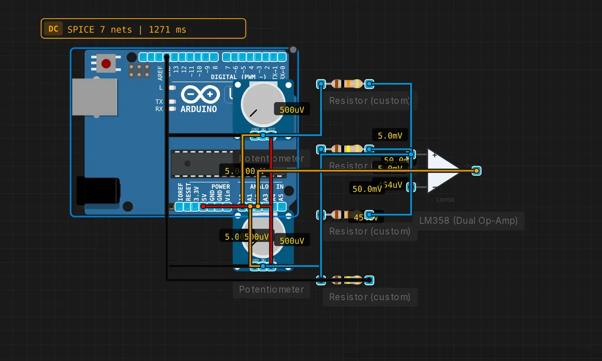
The exact circuit you get when you open this example — already wired, ready to run.
The sketch
// Difference amplifier — Gain=10, Vout = 10*(V2-V1)
void setup() { Serial.begin(9600); }
void loop() {
  float v1 = analogRead(A0) * 5.0 / 1023.0;
  float v2 = analogRead(A1) * 5.0 / 1023.0;
  float vout = analogRead(A2) * 5.0 / 1023.0;
  Serial.print("V1="); Serial.print(v1,2);
  Serial.print(" V2="); Serial.print(v2,2);
  Serial.print(" Vout="); Serial.println(vout,2);
  delay(500);
}
How it works
The op-amp is wired in the classic four-resistor difference configuration: R1 from V1 to the non-inverting input, R2 from that input to ground, R3 from V2 to the inverting input, R4 as feedback. With matched pairs, Vout = (R4/R3) × (V2 - V1) — gain 10 in this example.
The sketch reads V1 on A0, V2 on A1, and the output on A2, printing all three every 500 ms. The relationship between the three numbers is the lesson: the output equals ten times the difference of the two inputs, and noise on both inputs disappears from the output column.
Before you build it for real
The common-mode rejection lives and dies by resistor matching: four 5% resistors give only ~25 dB of rejection — the common-mode noise leaks straight through. The input common-mode range limits the circuit: with a single 5 V supply, both inputs must stay inside the op-amp’s valid range, or the output pegs to a rail silently. And the output swing cannot reach the rails on an LM358 — the computed Vout clips about 1.5 V short of 5 V, so a 0.4 V difference already saturates this gain-of-10 stage.
Get the parts
Related examples
FAQ
How does the difference amplifier reject common noise?
It amplifies only the voltage between V2 and V1. Any noise present equally on both inputs — power supply ripple, ground bounce, interference picked up by both wires — is common-mode and cancels out. That rejection is why bridge sensors and long differential signal runs use this topology.
Why does the resistor matching matter so much?
The common-mode rejection depends on the resistor ratios matching exactly. With 1% resistors, the rejection is about 40 dB; with 0.1% parts, it approaches 60 dB. A mismatch lets a fraction of the common-mode voltage leak into the output, which is exactly the noise the circuit is meant to suppress.