
Optocoupler Signal Isolation
Optocoupler Signal Isolation is a runnable microcontroller simulation example on SensBench — open the wired circuit, inspect the code, and compile real firmware in your browser, no install needed. Last updated Aug 14, 2026.
FREE SIMULATOR EXAMPLE · INTERMEDIATE
Optocoupler Signal Isolation
This example demonstrates a 4N25 optocoupler on the Arduino Uno: pin 9 lights the internal LED, and the phototransistor on the isolated side follows — the MCU and the isolated circuit share no electrical connection. The signal crosses as light.
| Board | Arduino Uno (ATmega328P) + logic / power circuit |
|---|---|
| Difficulty | intermediate |
| Category | circuits |
| Libraries | None — just the Arduino core |
| Runs in | Sensbench browser simulator — free, no account |
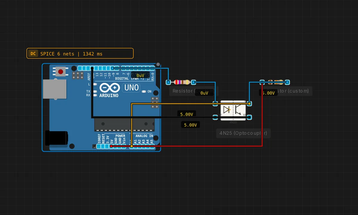
The exact circuit you get when you open this example — already wired, ready to run.
The sketch
// Optocoupler 4N25 — MCU drives LED side, reads phototransistor side
void setup() { pinMode(9,OUTPUT); Serial.begin(9600); }
void loop() {
  digitalWrite(9,HIGH); delay(500);
  int val = analogRead(A0);
  Serial.print("Isolated signal: "); Serial.println(val);
  digitalWrite(9,LOW); delay(500);
  val = analogRead(A0);
  Serial.print("Isolated signal: "); Serial.println(val);
}
How it works
Pin 9 drives the 4N25’s internal LED through a resistor. The phototransistor on the isolated side conducts when the LED is on, pulling its collector signal down — the A0 reading drops. The sketch alternates the LED on for 500 ms and off for 500 ms, reading and printing the isolated side’s value in each state.
The two printed values — low when the LED is on, high when off — are the isolation working: the MCU side toggles, and the change appears on the other side through light alone. The serial printout is the observer at the isolated boundary, watching the signal cross the gap.
Before you build it for real
The phototransistor is slow compared to the LED side: the 4N25’s current transfer ratio is only 20-50%, and its turn-off time is tens of microseconds — fine at 1 Hz, hopeless for fast digital signals, where high-speed optocouplers (6N137-class) take over. The isolation rating degrades with board contamination: flux, moisture and tight spacing shrink the effective gap, which is why optocouplers sit in slots and keepouts on serious PCBs. And the two sides need separate supplies — sharing a ground wire between the isolated circuit and the MCU destroys the isolation the component is providing.
Get the parts
Related examples
FAQ
How does an optocoupler isolate?
The signal crosses an internal gap as light: the MCU lights an internal LED, and a phototransistor on the other side sees it and conducts. There is no electrical connection between the two sides — the isolation voltage rating (typically 2500-5000 V) is the gap’s breakdown limit. That is what makes it the standard firewall between logic and dangerous circuits.
Why not just use a relay?
Both isolate, but an optocoupler switches in microseconds, never wears out mechanically, and handles signals a relay cannot follow. The trade-off: the phototransistor’s current handling is small, so heavy loads still need a transistor or relay downstream. The optocoupler is the signal isolator; the relay is the power switch.