
[Pi 5] Traffic Light
[Pi 5] Traffic Light is a runnable microcontroller simulation example on SensBench — open the wired circuit, inspect the code, and compile real firmware in your browser, no install needed. Last updated Aug 14, 2026.
FREE SIMULATOR EXAMPLE · INTERMEDIATE
[Pi 5] Traffic Light
This example runs a red/yellow/green traffic-light state machine on the Raspberry Pi 5 — three LEDs on GPIO17/27/22 with a 3-3-1 second cycle. Upload the Python script, run it, and the emulated intersection cycles forever.
| Board | Raspberry Pi 5 (Cortex-A76 + RP1 southbridge, QEMU-emulated Linux) |
|---|---|
| Difficulty | intermediate |
| Category | basics |
| Libraries | None — just the Arduino core |
| Runs in | Sensbench browser simulator — free, no account |
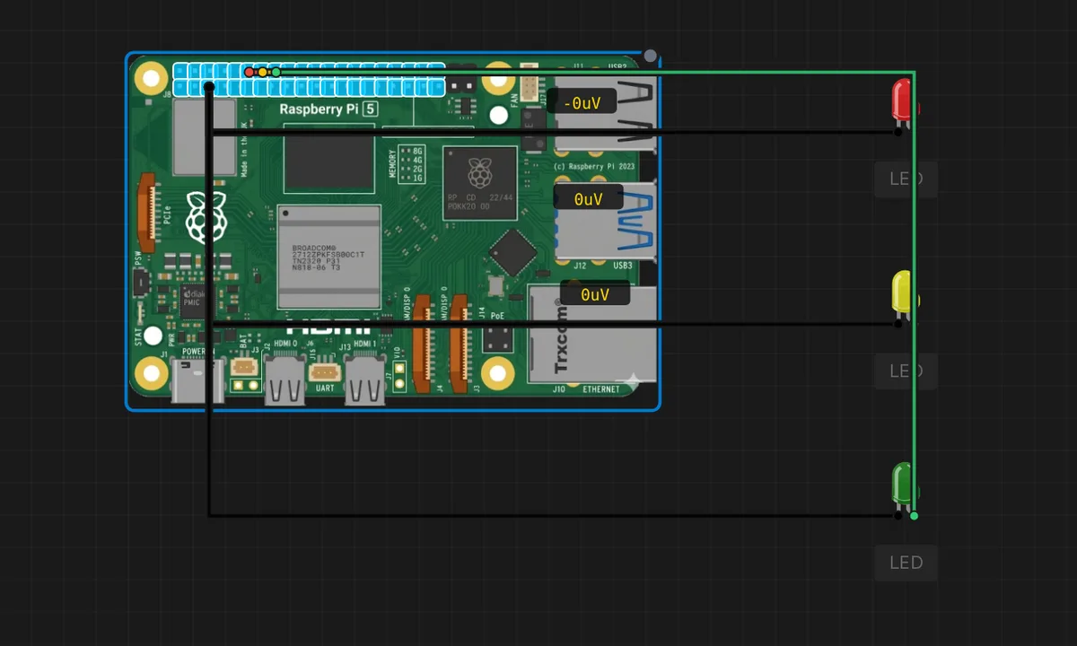
The exact circuit you get when you open this example — already wired, ready to run.
The Python script
#!/usr/bin/env python3
# Raspberry Pi 5 - Traffic light state machine
# Wiring: red->GPIO17, yellow->GPIO27, green->GPIO22 (each LED- -> GND).
from gpiozero import LED
from time import sleep

red = LED(17)
yellow = LED(27)
green = LED(22)
print("Traffic light running - Ctrl-C to stop")
try:
    while True:
        red.on(); yellow.off(); green.off()
        print("RED")
        sleep(3)
        red.off(); green.on()
        print("GREEN")
        sleep(3)
        green.off(); yellow.on()
        print("YELLOW")
        sleep(1)
        yellow.off()
except KeyboardInterrupt:
    red.off(); yellow.off(); green.off()
    print("Stopped")
How it works
Three gpiozero LED objects — red on GPIO17, yellow on GPIO27, green on GPIO22 — are driven by an explicit state machine. Each loop iteration sets exactly one LED on and the others off, prints the active color, and sleeps: red 3 s, green 3 s, yellow 1 s. The single-LED-on discipline is the whole logic.
The state machine is written as three explicit transitions rather than a table, which keeps the example beginner-approachable. The KeyboardInterrupt handler turns all three LEDs off on exit — a small courtesy that prevents a real Pi from being left with a glowing red after Ctrl-C.
Before you build it for real
Three LEDs on a real bench means three series resistors (220 Ohm each) — the simulator’s bare LEDs are free, real silicon is not. The three pins pull about 30 mA total from the 3.3 V rail, well within budget, but the moment you add more peripherals the 50 mA rail cap starts to matter. GPIO22 sits next to several I2C-capable pins on the header; double-check each BCM number against the physical pinout before wiring, because GPIO27 and GPIO22 are not adjacent on the header despite the tidy code.
Get the parts
Related examples
FAQ
Why this red, green, yellow sequence?
It is a simplified traffic cycle: red for 3 seconds, green for 3 seconds, yellow for 1 second, then repeat. Real intersections interleave left-turn arrows and all-red clearance phases; the 3-3-1 timing here is the teaching version, long enough to read each state clearly.
Why use three separate LED objects instead of a list?
Named objects (red, yellow, green) make the state machine readable: red.on(); yellow.off(); green.off() reads like English. A list would be more compact but less obvious. Either works; readability wins for a demo whose point is the sequence itself.