
Pico: NTC Thermistor Temperature
Pico: NTC Thermistor Temperature is a runnable microcontroller simulation example on SensBench — open the wired circuit, inspect the code, and compile real firmware in your browser, no install needed. Last updated Aug 14, 2026.
FREE SIMULATOR EXAMPLE · INTERMEDIATE
Pico: NTC Thermistor Temperature
This example reads temperature from an NTC 10k thermistor wired into a voltage divider on the Pico’s ADC pin A0 (GP26). The sketch converts the raw ADC reading to resistance, then to degrees Celsius using the Steinhart-Hart equation — the same math used in real thermistor designs.
| Board | Raspberry Pi Pico (RP2040 dual-core Cortex-M0+, 133 MHz) |
|---|---|
| Difficulty | intermediate |
| Category | sensors |
| Libraries | None — just the Arduino core |
| Runs in | Sensbench browser simulator — free, no account |
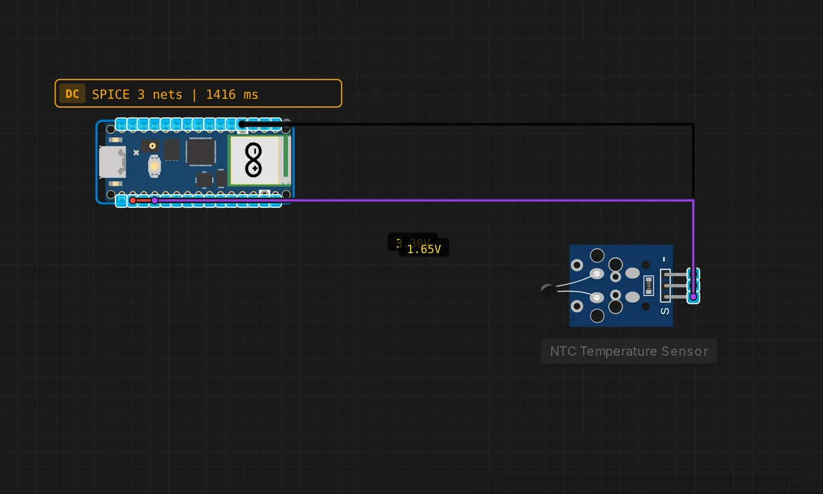
The exact circuit you get when you open this example — already wired, ready to run.
The sketch
// Raspberry Pi Pico — NTC Thermistor Temperature Sensor
// Wiring: OUT → A0 (GP26)  |  VCC → 3.3V  |  GND → GND

#define NTC_PIN A0  // GP26 on Pico

const float VCC        = 3.3;
const float SERIES_R   = 10000.0;
const float NOM_R      = 10000.0;
const float B_COEFF    = 3950.0;
const float NOM_TEMP_K = 298.15; // 25 °C

float readTempC() {
  int   raw = analogRead(NTC_PIN);
  float v   = raw * (VCC / 1023.0);
  // VCC → R_pull → A1 → R_NTC → GND (the divider sensbench models)
  float r   = SERIES_R * v / (VCC - v);
  float st  = log(r / NOM_R) / B_COEFF + 1.0 / NOM_TEMP_K;
  return (1.0 / st) - 273.15;
}

void setup() {
  Serial.begin(115200);
  analogReadResolution(10);
  Serial.println("Pico NTC Temperature Sensor");
}

void loop() {
  float tc = readTempC();
  Serial.print("Temperature: "); Serial.print(tc, 2); Serial.println(" C");
  delay(1000);
}
How it works
The NTC thermistor forms a voltage divider with the fixed 10 kOhm series resistor: VCC to R_pull, then the ADC pin, then R_NTC to GND. As temperature rises the thermistor resistance drops, pulling the ADC voltage down. The code converts the raw 10-bit ADC reading to a voltage with v = raw * (VCC / 1023.0), then solves the divider for the thermistor resistance: r = SERIES_R * v / (VCC - v).
The resistance is then converted to temperature with the B-parameter Steinhart-Hart equation: 1/T = 1/T0 + ln(R/R0)/B. The code computes st = log(r / NOM_R) / B_COEFF + 1.0 / NOM_TEMP_K and returns (1.0 / st) - 273.15. The ADC is set to 10-bit resolution — the RP2040 is natively 12-bit, but 10 bits is plenty for a sensor with a slow thermal response.
Before you build it for real
The divider is only as accurate as its reference. The code assumes VCC = 3.3 V exactly, but on a real Pico the 3.3 V rail from USB can drift a few percent with load — that error lands directly on your temperature reading. A 1% tolerance series resistor matters more than you expect: with a 5% resistor, the temperature error can exceed 1 C near the extremes. On real hardware the NTC is a passive component with self-heating — keep the current through it below ~1 mA or the thermistor warms itself and reads a few degrees high.
Get the parts
Related examples
FAQ
Why use the Steinhart-Hart equation instead of a lookup table?
A lookup table would need dozens of entries to cover the same temperature range with the same accuracy. The Steinhart-Hart equation is a single continuous formula that maps resistance to temperature anywhere on the curve, and the B-coefficient version used here needs only two parameters: the nominal resistance at 25 C (10 kOhm) and the B coefficient (3950).
What happens if I use a different series resistor?
The divider math still works — the code solves for the thermistor resistance using SERIES_R, so a 4.7 kOhm or 47 kOhm pull-up is fine as long as you update the constant. Larger series resistors give more sensitivity at lower temperatures, smaller ones at higher temperatures, but the measurement noise also changes, so 10 kOhm is a sensible default.