
Raspberry Pi Pico: Stepper + A4988
Raspberry Pi Pico: Stepper + A4988 is a runnable microcontroller simulation example on SensBench — open the wired circuit, inspect the code, and compile real firmware in your browser, no install needed. Last updated Aug 14, 2026.
FREE SIMULATOR EXAMPLE · INTERMEDIATE
Raspberry Pi Pico: Stepper + A4988
This example spins a bipolar stepper motor from the Raspberry Pi Pico through an A4988 driver board — STEP on GP3, DIR on GP4. It produces a continuous 625-step-per-second pulse train, the minimal building block every stepper project is built from.
| Board | Raspberry Pi Pico (RP2040 dual-core Cortex-M0+, 133 MHz) |
|---|---|
| Difficulty | intermediate |
| Category | motors |
| Libraries | None — just the Arduino core |
| Runs in | Sensbench browser simulator — free, no account |
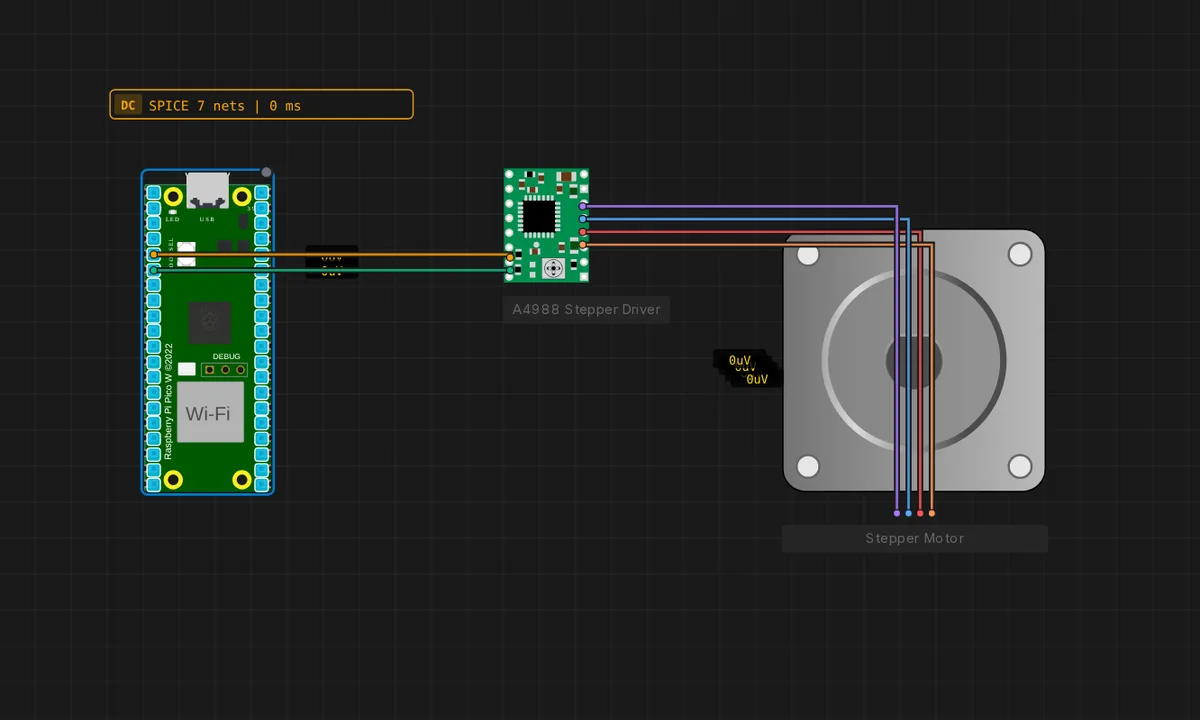
The exact circuit you get when you open this example — already wired, ready to run.
The sketch
// Raspberry Pi Pico + A4988 stepper driver (STEP/DIR)
// GP3 -> STEP, GP4 -> DIR.
const int STEP_PIN = 3, DIR_PIN = 4;

void setup() {
  pinMode(STEP_PIN, OUTPUT);
  pinMode(DIR_PIN, OUTPUT);
  digitalWrite(DIR_PIN, HIGH);
  Serial.begin(115200);
  Serial.println("A4988 stepper running");
}

void loop() {
  digitalWrite(STEP_PIN, HIGH);
  delayMicroseconds(800);
  digitalWrite(STEP_PIN, LOW);
  delayMicroseconds(800);
}
How it works
The sketch configures GP3 as STEP and GP4 as DIR, then loops forever producing a 50% duty square wave: 800 us HIGH, 800 us LOW. Every rising edge of the STEP signal makes the A4988 advance the motor one step. DIR is set HIGH once in setup(), which fixes the direction — flip that one line and the motor spins the other way.
The delayMicroseconds(800) value sets the step rate: shorter delays mean faster stepping, down to the A4988’s minimum pulse width (about 1 us). The 1.6 ms period is comfortable for a 12 V NEMA-17 — fast enough to show real rotation, slow enough that the driver’s microstep timing stays clean. The Serial.println() in setup confirms the sketch started without cluttering the loop.
Before you build it for real
The A4988 is a bare driver, not a module with protections: on a real build you must add a large electrolytic capacitor (100 uF or more) across VMOT/GND near the driver, or the motor’s back-EMF will crash the driver during direction changes. The motor power supply (8-35 V for the A4988) is completely separate from the Pico’s 3.3 V logic — only the ground is common, and current for the motor never flows through the RP2040. Also check the driver’s current-limit potentiometer: out of the box it often defaults too high for small steppers and the motor will overheat. And never connect or disconnect the motor while powered — that is how A4988s die.
Get the parts
Related examples
FAQ
Why does the A4988 need STEP and DIR only?
The A4988 is a stepper driver, not a controller: it takes a step pulse on STEP and a direction level on DIR, and internally sequences the motor’s four coil phases. The MCU never touches the coils directly — the driver handles the high-current switching.
How fast is this motor spinning?
The loop generates one pulse every 1.6 ms (800 us high + 800 us low), so about 625 steps per second. In full-step mode the A4988 moves 200 steps per revolution, giving about 3.1 revolutions per second — visibly fast, and typical for a demo.