
7805 Regulated Power Supply
7805 Regulated Power Supply is a runnable microcontroller simulation example on SensBench — open the wired circuit, inspect the code, and compile real firmware in your browser, no install needed. Last updated Aug 14, 2026.
FREE SIMULATOR EXAMPLE · BEGINNER
7805 Regulated Power Supply
This example demonstrates a 7805 linear regulator on the Arduino Uno: a 9 V battery feeds it, and the ADC reads the regulated 5 V output. Watch the reading stay flat as the input sags — until the battery drops past the dropout point.
| Board | Arduino Uno (ATmega328P) + logic / power circuit |
|---|---|
| Difficulty | beginner |
| Category | circuits |
| Libraries | None — just the Arduino core |
| Runs in | Sensbench browser simulator — free, no account |
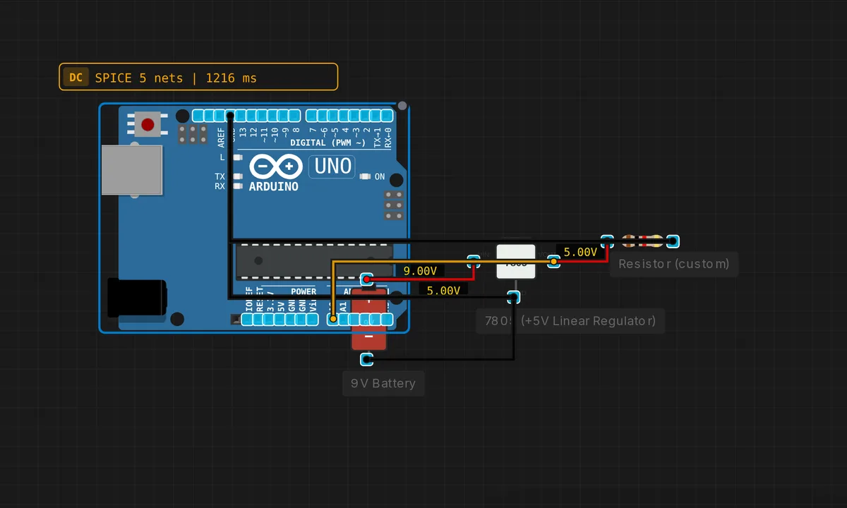
The exact circuit you get when you open this example — already wired, ready to run.
The sketch
// 7805 power supply — regulated 5V from 9V battery
// The 7805 provides stable 5V regardless of battery voltage (7-12V range)
void setup() { Serial.begin(9600); }
void loop() {
  float v = analogRead(A0) * 5.0 / 1023.0;
  Serial.print("Regulated voltage: "); Serial.print(v,2); Serial.println(" V");
  delay(1000);
}
How it works
The 9 V battery feeds the 7805’s input; the regulator holds 5 V at its output, which powers the load — and the Arduino’s ADC reads that output on A0. The sketch prints the regulated voltage once per second, with the comment spelling out the 7-12 V input window the regulator accepts.
The reading is nominally 5.00 V and stays there as the input sags — the flat line in the face of a falling battery is the regulation working. When the battery drops below the regulator’s dropout voltage (about 7 V for a 7805), the output begins to sag with it, and the printed value starts falling — the end-of-battery warning in disguise.
Before you build it for real
The 7805 burns the input-output difference as heat: at 9 V input and 500 mA load it dissipates 2 W — too hot to touch, and exactly why the TO-220 package carries a heatsink tab. The dropout voltage (~2 V) sets the battery floor: below 7 V the output falls with the input, and the “regulated” supply silently becomes unregulated. The regulator also needs capacitors at both input and output (typically 0.33 uF in, 0.1 uF out) to stay stable — omit them and the 7805 can oscillate. And the input must stay under ~35 V: beyond that the part fails, often catastrophically.
Get the parts
Related examples
FAQ
What does the 7805 actually do?
It is a linear regulator: it takes any input from about 7-12 V and actively holds its output at 5 V by dissipating the difference as heat. A 9 V battery sags as it drains, and the 7805 smooths that into a rock-steady 5 V — the same regulator that sat on the Arduino’s own board for years.
Why does the sketch read the regulator's own output?
It is a verification loop: the ADC measures the very rail the measurement assumes. The printed “Regulated voltage” should sit at 5.00 V and stay there while the battery droops — the entire promise of regulation demonstrated against the meter itself.