
RC Low-Pass Filter
RC Low-Pass Filter is a runnable microcontroller simulation example on SensBench — open the wired circuit, inspect the code, and compile real firmware in your browser, no install needed. Last updated Aug 14, 2026.
FREE SIMULATOR EXAMPLE · BEGINNER
RC Low-Pass Filter
This example filters a PWM output into a smooth analog voltage: pin 9 drives 50% PWM through a 10 kOhm resistor and 10 uF capacitor, and the Arduino reads the result on A0 — a classic poor-man’s DAC. Change the duty cycle and watch the filtered level follow.
| Board | Arduino Uno (ATmega328P) + analog SPICE circuit |
|---|---|
| Difficulty | beginner |
| Category | circuits |
| Libraries | None — just the Arduino core |
| Runs in | Sensbench browser simulator — free, no account |
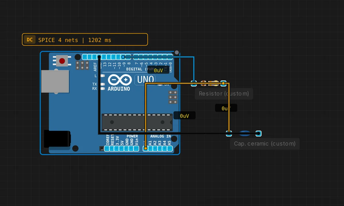
The exact circuit you get when you open this example — already wired, ready to run.
The sketch
// RC Low-Pass Filter
// PWM on pin 9 → R=10k → C=10uF → smooth DC on A0
// DC steady-state: V_out ≈ duty × Vcc = 0.5 × 5 = 2.5 V
void setup() { Serial.begin(9600); analogWrite(9, 128); } // 50% duty
void loop() {
  float v = analogRead(A0) * 5.0 / 1023.0;
  Serial.print("Filtered V = "); Serial.println(v, 2);
  delay(200);
}
How it works
The sketch sets pin 9 to 50% PWM with analogWrite(9, 128), and the RC network — 10 kOhm in series, 10 uF to ground — smooths the pulses into DC. The corner frequency is 1/(2πRC) ≈ 1.6 Hz, far below the ~490 Hz PWM rate, so the filter passes the average and suppresses the pulses.
The loop reads A0 and prints the filtered voltage every 200 ms. The steady-state reading should sit near 2.5 V; if you change the duty cycle in analogWrite(), the filtered level follows — a live demonstration that PWM plus RC is a poor man’s DAC. The 200 ms poll gives the filter time to track changes between reads.
Before you build it for real
The RC filter is slow by design: with a 10 kOhm/10 uF pair the time constant is 100 ms, so the output takes about half a second to settle after a duty-cycle change. Ripple is the other tax: the capacitor never fully smooths the PWM train, and the residual ripple is proportional to C and inversely to the PWM frequency. The ATmega328P’s analogWrite() runs PWM at ~490 Hz — low enough that ripple is visible; using Timer1 at a higher frequency shrinks it. And electrolytic capacitors have tolerance: a “10 uF” cap is often 20% off, shifting the corner frequency and the settling time.
Get the parts
Related examples
FAQ
Why does the filter settle at exactly 2.5 V?
The PWM is set to 50% duty, and a low-pass filter averages the pulses: the steady-state DC is duty × Vcc = 0.5 × 5 = 2.5 V. That is the whole trick of PWM-to-analog: the capacitor integrates the on/off train into its average, and the average is set by the duty cycle.
How is this different from a real DAC?
A real DAC outputs a precise analog level instantly. The RC filter is cheap but slow (it takes several time constants to settle) and has ripple — the residual AC that never fully smooths. For audio or sensor bias it is often good enough; for precision references you want a real DAC.