
Relay-Controlled LED
Relay-Controlled LED is a runnable microcontroller simulation example on SensBench — open the wired circuit, inspect the code, and compile real firmware in your browser, no install needed. Last updated Aug 14, 2026.
FREE SIMULATOR EXAMPLE · INTERMEDIATE
Relay-Controlled LED
This example drives a relay through an NPN transistor on the Arduino Uno — the MCU flips a magnetic coil, and the relay’s contacts switch an LED on a completely separate supply. The classic isolation pattern for controlling circuits the Arduino should never touch directly.
| Board | Arduino Uno (ATmega328P) + logic / power circuit |
|---|---|
| Difficulty | intermediate |
| Category | circuits |
| Libraries | None — just the Arduino core |
| Runs in | Sensbench browser simulator — free, no account |
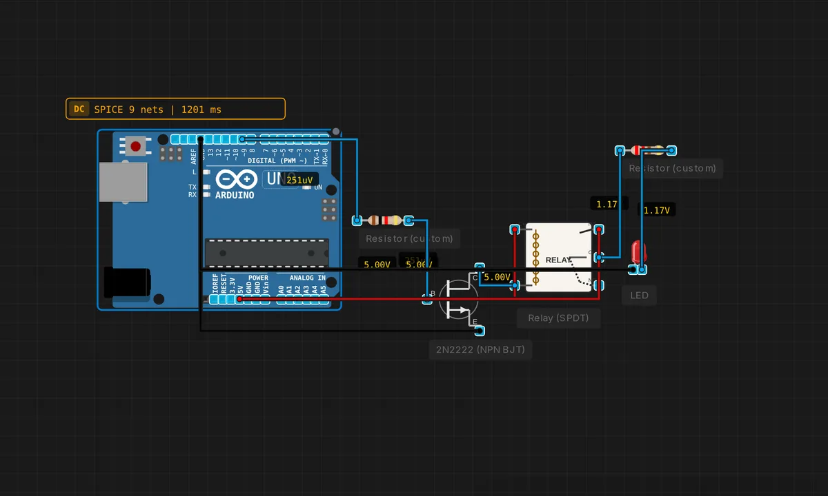
The exact circuit you get when you open this example — already wired, ready to run.
The sketch
// Relay control via NPN transistor
void setup() { pinMode(9, OUTPUT); }
void loop() {
  digitalWrite(9, HIGH); delay(2000); // relay ON
  digitalWrite(9, LOW);  delay(2000); // relay OFF
}
How it works
Pin 9 drives the NPN transistor’s base through the usual resistor. HIGH saturates the transistor, current flows through the relay coil, the magnetic field closes the contacts, and the separate supply’s LED lights. LOW releases the coil, the contacts open, and the LED goes dark. The 2-second phases make each state observable.
The relay is the electromechanical translation of a logic level into a physical switch — the code is a plain on/off, and the interesting parts are all hardware: the coil, the magnetic field, and the contacts closing with an audible click on real hardware.
Before you build it for real
The relay coil’s flyback spike is the killer detail: when the transistor turns off, the coil’s collapsing magnetic field induces a voltage spike — hundreds of volts in a small coil — that can destroy the transistor in one cycle. A real build needs a flyback diode across the coil (cathode to supply), which the schematic should always include. The contacts also wear out: relays have a finite mechanical life (often 100k-1M operations), so do not PWM a relay — this example’s 2-second cycle is fine, fast switching kills it. And the contacts arc under inductive loads, which is why the relay’s contact rating is a separate spec from its coil rating.
Get the parts
Related examples
FAQ
Why drive the relay through a transistor?
A relay coil needs 30-100 mA to pull in — far beyond the ATmega328P’s per-pin limit. The NPN transistor becomes the coil switch: the pin supplies only the small base current, and the transistor sinks the coil current from the supply. The relay and the MCU are electrically separate circuits with the transistor as the bridge.
What is the point of the separate supply?
Isolation. The relay’s contacts switch a completely independent circuit — often a different voltage (mains, 12 V automotive, another device’s power). The MCU never touches that circuit; it only controls the magnetic coil. That separation is why relays survive in designs where solid-state switches would not.