
STM32: 7-Segment Counter
STM32: 7-Segment Counter is a runnable microcontroller simulation example on SensBench — open the wired circuit, inspect the code, and compile real firmware in your browser, no install needed. Last updated Aug 14, 2026.
FREE SIMULATOR EXAMPLE · BEGINNER
STM32: 7-Segment Counter
This example counts from 0 to 9 on a 7-segment display driven by seven GPIO pins (PA0-PA6) of the STM32 Blue Pill. Each digit is a bitmask written to the segment pins, with the current digit printed to the Serial Monitor every 800 ms.
| Board | STM32 Blue Pill (STM32F103C8, Cortex-M3, 72 MHz) |
|---|---|
| Difficulty | beginner |
| Category | basics |
| Libraries | None — just the Arduino core |
| Runs in | Sensbench browser simulator — free, no account |
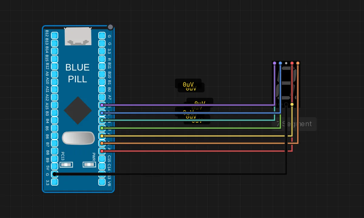
The exact circuit you get when you open this example — already wired, ready to run.
The sketch
// STM32 Blue Pill (F103) — 7-segment counter 0-9
// Segments A..G on PA0..PA6, common cathode (COM -> GND).
const int seg[7] = { PA0, PA1, PA2, PA3, PA4, PA5, PA6 }; // A B C D E F G
// Bit i (i=0..6) maps to segment seg[i]. 1 = segment lit.
const uint8_t pattern[10] = {
  0x3F, 0x06, 0x5B, 0x4F, 0x66, 0x6D, 0x7D, 0x07, 0x7F, 0x6F
};

void setup() {
  Serial.begin(115200);
  for (int i = 0; i < 7; i++) pinMode(seg[i], OUTPUT);
}

void loop() {
  for (int d = 0; d < 10; d++) {
    uint8_t p = pattern[d];
    for (int i = 0; i < 7; i++) digitalWrite(seg[i], (p >> i) & 1);
    Serial.print("digit = "); Serial.println(d);
    delay(800);
  }
}
How it works
Seven pins PA0-PA6 map to segments A-G, and a pattern array stores one bitmask per digit: 0x3F for 0, 0x06 for 1, and so on through 0x6F for 9. The loop walks digits 0-9, and for each one shifts the mask out bit by bit with (p >> i) & 1 to drive the seven segment pins.
The digitalWrite() per segment makes the code longer than an LCD sketch would be, but it shows exactly what a 7-segment driver does under the hood. The Serial print confirms the digit on the canvas matches the code’s intention, and the 800 ms delay gives each digit a readable pause.
Before you build it for real
Every segment is an LED and every LED wants its own series resistor — seven segments at roughly 10 mA each is 70 mA, near the F103’s comfortable output budget, so plan the resistor values (around 220 Ohm each) before wiring a real display. The simulator shows a common-cathode display with COM to GND; a common-anode display inverts every pattern bit. And a real 7-segment is usually driven via a shift register or driver chip because seven pins per digit does not scale — this direct-drive wiring is fine for one digit and the teaching value of seeing every pin move.
Get the parts
Related examples
FAQ
How do the hex pattern values encode digits?
Each byte is a bitmask where bit i controls segment i (A..G on PA0..PA6). For example 0x3F = 0b0111111 lights segments A-F which spells 0, and 0x06 lights B and C which spells 1. The hex table is compact and standard — the same pattern arrays appear in Arduino, PIC and AVR libraries.
Why only 10 digits instead of 16?
The pattern table could easily include A-F for hex counting — the array just stops at 9. Extending it is a one-line table addition. The example keeps decimal counting to match the beginner level, but the display hardware itself does not care.