
STM32 Blue Pill Blink
STM32 Blue Pill Blink is a runnable microcontroller simulation example on SensBench — open the wired circuit, inspect the code, and compile real firmware in your browser, no install needed. Last updated Aug 14, 2026.
FREE SIMULATOR EXAMPLE · BEGINNER
STM32 Blue Pill Blink
This example blinks the STM32 Blue Pill’s onboard LED on PC13 and prints a banner to the Serial Monitor — the STM32 equivalent of hello world. The LED is active-LOW, so the code is the mirror image of an Arduino blink, which is the first lesson this board teaches.
| Board | STM32 Blue Pill (STM32F103C8, Cortex-M3, 72 MHz) |
|---|---|
| Difficulty | beginner |
| Category | basics |
| Libraries | None — just the Arduino core |
| Runs in | Sensbench browser simulator — free, no account |
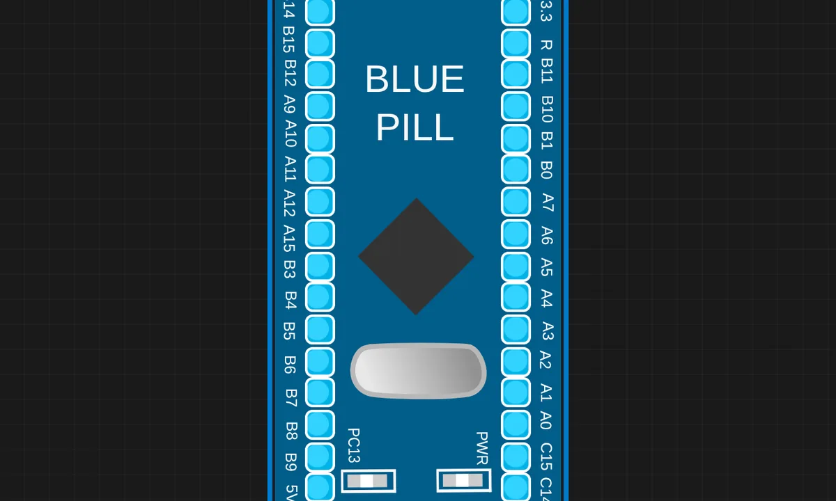
The exact circuit you get when you open this example — already wired, ready to run.
The sketch
// STM32 Blue Pill (STM32F103C8) blink + serial
// Onboard LED is on PC13 (active LOW). Runs under QEMU via libqemu-arm.

void setup() {
  pinMode(PC13, OUTPUT);
  Serial.begin(115200);
  Serial.println("SENSBENCH STM32 blink");
}

void loop() {
  digitalWrite(PC13, HIGH);
  delay(200);
  digitalWrite(PC13, LOW);
  delay(200);
}
How it works
pinMode(PC13, OUTPUT) configures the pin — note the PC prefix: STM32 pins are named by port and pin number, not by a single number like Arduino. Serial.begin(115200) starts USART1, and the loop alternates HIGH and LOW with 200 ms delays. Because the LED is active-LOW, the visible effect is a fast blink — 200 ms on, 200 ms off, roughly 2.5 Hz.
The Serial.println() in setup prints a startup banner to the monitor. The loop itself is pure GPIO toggling — no serial traffic — which keeps the example as minimal as the blink it demonstrates. Under QEMU the toggling happens at real ARM clock rates, so the delay timing is exact.
Before you build it for real
The active-LOW PC13 LED is the classic trap: on a real Blue Pill, writing HIGH turns the LED OFF. Also, this is a 3.3 V board — feeding 5 V into any GPIO, including through a pull-up resistor, damages the STM32F103’s pins. And under QEMU the example tolerates sloppy timing and floating pins that real silicon does not: a real Blue Pill with nothing connected to the serial port still runs fine, but connecting 5 V peripherals to the 3.3 V logic will not.
Related examples
FAQ
Why is the onboard LED on PC13 active-LOW?
The Blue Pill’s PCB connects the LED between PC13 and 3.3 V with the current flowing out of the pin — so writing LOW lights it and HIGH turns it off. This is the opposite of the Arduino convention and the first thing that confuses STM32 newcomers: a sketch that writes HIGH “turns the LED on” on an Uno does nothing visible here.
What does QEMU mean for this example?
The STM32 Blue Pill runs under QEMU ARM emulation — the entire Cortex-M3 core is simulated. Pin behavior, timing and serial output are modeled faithfully, so the sketch behaves like the real chip; the main difference you will notice is that flash and RAM limits are not the hard wall they are on real silicon.