
STM32 Serial Counter
STM32 Serial Counter is a runnable microcontroller simulation example on SensBench — open the wired circuit, inspect the code, and compile real firmware in your browser, no install needed. Last updated Aug 14, 2026.
FREE SIMULATOR EXAMPLE · BEGINNER
STM32 Serial Counter
This example turns the STM32 Blue Pill into a living heartbeat: every second it prints an incrementing counter and the raw uptime in milliseconds to the Serial Monitor, while the onboard PC13 LED blinks at 1 Hz. It is the standard “is my board still alive” test for the F103.
| Board | STM32 Blue Pill (STM32F103C8, Cortex-M3, 72 MHz) |
|---|---|
| Difficulty | beginner |
| Category | communication |
| Libraries | None — just the Arduino core |
| Runs in | Sensbench browser simulator — free, no account |
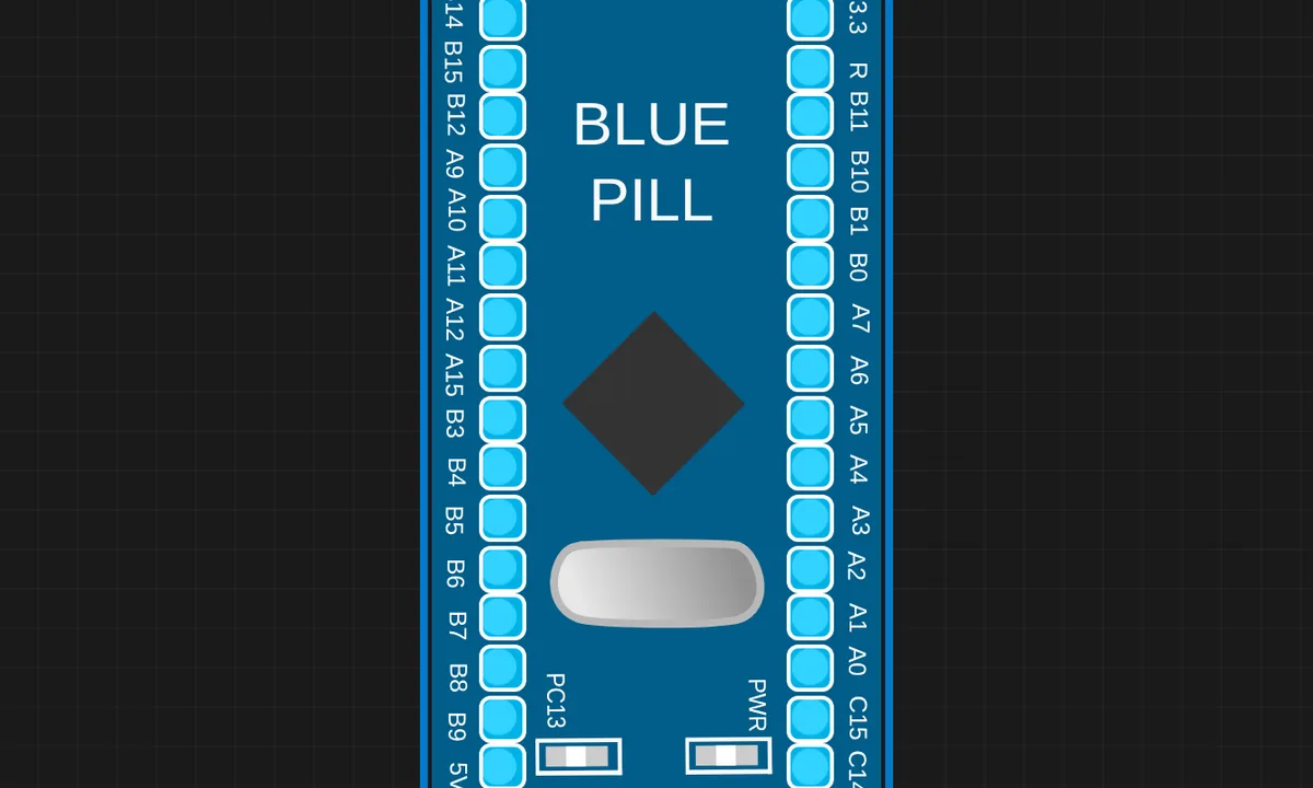
The exact circuit you get when you open this example — already wired, ready to run.
The sketch
// STM32 Blue Pill — serial counter (USART1, 115200 baud)
unsigned long n = 0;

void setup() {
  Serial.begin(115200);
  pinMode(PC13, OUTPUT);
  Serial.println("STM32 Blue Pill ready");
}

void loop() {
  n++;
  Serial.print("count=");
  Serial.print(n);
  Serial.print("  uptime_ms=");
  Serial.println(millis());
  digitalWrite(PC13, n % 2 ? HIGH : LOW);  // heartbeat
  delay(1000);
}
How it works
A global unsigned long n increments every loop, and the sketch prints count=n plus uptime_ms=millis() once per second thanks to the delay(1000) at the end of the loop. The PC13 heartbeat uses n % 2 to toggle — odd counts light it, even counts darken it — making the 1 Hz loop rate visible even with the monitor closed.
Because millis() returns the raw uptime in milliseconds, the printed number grows fast — after a minute it reads 60000. That is intentional: it gives you the real elapsed time without any time conversion code, and the Serial Monitor’s auto-scroll keeps the latest values in view.
Before you build it for real
This sketch is the victim of the active-LOW PC13 trap in reverse: the heartbeat looks inverted compared to an Arduino blink because HIGH is OFF. If you copy the pattern to another STM32 board with an active-HIGH LED (some Black Pills, the F4 Discovery), the heartbeat logic reads backwards. Also, millis() on the STM32 core wraps after about 49.7 days (32-bit unsigned) — fine for a counter demo, but production code that computes intervals must use unsigned subtraction, not comparisons, so the wrap is harmless.
Related examples
FAQ
Why print uptime_ms instead of just a counter?
The counter proves the loop iterates; the uptime in milliseconds proves the timing is real. On a real Blue Pill, if the uptime keeps climbing while the counter increments, the core is stable. Together they are a cheap watchdog sanity check — the uptime number should never reset without a reboot.
What is the heartbeat blink for?
The PC13 LED toggles every second using n % 2 — odd counts light it, even counts darken it. With the Serial Monitor closed, the heartbeat is the only visible proof the sketch is alive; it also makes the 1 Hz loop rate obvious at a glance.