
[STM32 + ESP32] GPIO Sync
[STM32 + ESP32] GPIO Sync is a runnable microcontroller simulation example on SensBench — open the wired circuit, inspect the code, and compile real firmware in your browser, no install needed. Last updated Aug 14, 2026.
FREE SIMULATOR EXAMPLE · ADVANCED
[STM32 + ESP32] GPIO Sync
This example syncs an STM32 Blue Pill with an ESP32 over a single GPIO wire: the Blue Pill toggles PA1 at 1 Hz, and the ESP32 reads it on GPIO4 and mirrors it onto GPIO2 (the onboard LED). ARM and Xtensa cores talk through one simulated pin.
| Board | STM32 Blue Pill (STM32F103C8, Cortex-M3, 72 MHz) |
|---|---|
| Difficulty | advanced |
| Category | communication |
| Libraries | None — just the Arduino core |
| Runs in | Sensbench browser simulator — free, no account |
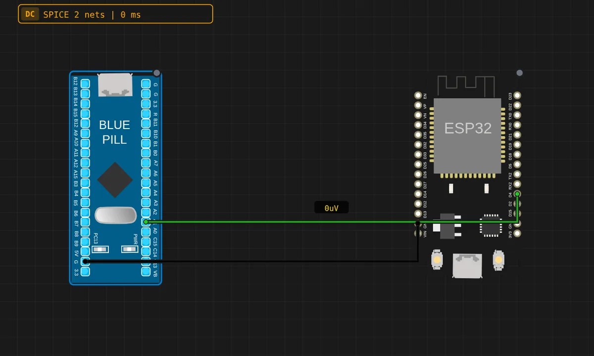
The exact circuit you get when you open this example — already wired, ready to run.
The sketch
// STM32 Blue Pill — drives PA1 at 1 Hz.
// Wiring: STM32 PA1 -> ESP32 GPIO4,  STM32 GND -> ESP32 GND.
void setup() {
  pinMode(PA1, OUTPUT);
  pinMode(PC13, OUTPUT);
  Serial.begin(115200);
}
void loop() {
  digitalWrite(PA1, HIGH); digitalWrite(PC13, LOW);
  Serial.println("PA1 HIGH"); delay(700);
  digitalWrite(PA1, LOW);  digitalWrite(PC13, HIGH);
  Serial.println("PA1 LOW");  delay(700);
}
How it works
The Blue Pill drives PA1 at 1 Hz (700 ms per level) with its PC13 LED as a local reference. The ESP32 reads GPIO4 and mirrors the level to GPIO2 — the onboard LED pin. Both boards run under QEMU: libqemu-arm for the STM32 and libqemu-xtensa for the ESP32, connected by a simulated wire.
The ESP32’s side is deliberately simple — read, mirror, repeat — because the interesting part is the transport: a 3.3 V ARM pin driving a 3.3 V Xtensa pin. With both boards at 3.3 V logic, the direct wire is electrically clean, and the two emulation engines stay in perfect agreement.
Before you build it for real
Both boards here are 3.3 V logic, so the direct wire is safe — the moment either end is a 5 V board, the level math changes and you need a shifter. The common ground is the wire people forget: without it the ESP32 has no reference to judge PA1 against. On real hardware, also remember the ESP32’s strapping pins: GPIO2 must read HIGH at boot, and if this sync circuit ever holds it LOW during power-up, the ESP32 enters the wrong boot mode — a failure the simulator never shows because it never powers the boards in sequence.
Get the parts
Related examples
FAQ
Why is the ESP32 involved at all?
This is the demo’s whole point: an ARM Cortex-M3 (STM32 QEMU) and an Xtensa LX6 (ESP32 QEMU) are completely different architectures, and the simulator runs both simultaneously over a shared wire. It proves the wire protocol — not the chip — is what makes boards talk.
Why does the ESP32 mirror onto GPIO2?
GPIO2 is the ESP32’s onboard LED pin on most DevKit boards. Reading GPIO4 and mirroring to GPIO2 gives you a visible receiver side: the STM32 prints “PA1 HIGH”, and the ESP32’s onboard LED lights in sync — a cross-architecture visual handshake.