
Netduino Plus 2 Blink
Netduino Plus 2 Blink is a runnable microcontroller simulation example on SensBench — open the wired circuit, inspect the code, and compile real firmware in your browser, no install needed. Last updated Aug 14, 2026.
FREE SIMULATOR EXAMPLE · BEGINNER
Netduino Plus 2 Blink
This example blinks the Netduino Plus 2’s onboard PA10 LED and prints a board banner to Serial. The board is a .NET Micro Framework classic powered by an STM32F405, and this sketch runs the Arduino core on it — the fastest way to confirm the toolchain works.
| Board | Netduino Plus 2 (STM32F405, Cortex-M4, 168 MHz) |
|---|---|
| Difficulty | beginner |
| Category | basics |
| Libraries | None — just the Arduino core |
| Runs in | Sensbench browser simulator — free, no account |
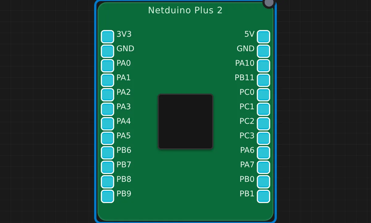
The exact circuit you get when you open this example — already wired, ready to run.
The sketch
// Netduino Plus 2 (STM32F405) — onboard LED on PA10 (active HIGH).

void setup() {
  pinMode(PA10, OUTPUT);
  Serial.begin(115200);
  Serial.println("SENSBENCH Netduino Plus 2");
}

void loop() {
  digitalWrite(PA10, HIGH);
  delay(300);
  digitalWrite(PA10, LOW);
  delay(300);
}
How it works
The Netduino Plus 2’s onboard LED lives on PA10 — an unusual pin that doubles as USART1 RX — and is active-HIGH. The sketch sets PA10 as output and blinks at 300 ms: 1.67 Hz, a relaxed rhythm for a status indicator.
The Serial.println() banner identifies the board at 115200 baud. Under QEMU the emulated STM32F405 executes the same Cortex-M4 instructions, and the blink timing is faithful — the 300 ms delay really is 300 ms.
Before you build it for real
The Netduino’s LED is on PA10, which is also USART1 RX — the same pin the Serial Monitor receives on. On real hardware, wiring a serial source to PA10 while the LED blinks on it creates a conflict: the LED driver fights the serial receiver on the same line. This example uses Serial only for output (TX is PA9), so it works, but adding serial input to this sketch will misbehave. The LED is active-HIGH, and the board is 3.3 V logic. Real Netduinos also had a bootloader dance (holding the button during reset) for firmware entry, which the QEMU model skips entirely.
Related examples
FAQ
What is a Netduino?
The Netduino Plus 2 is a .NET Micro Framework board from the early 2010s — an STM32F405 in an Arduino-like form factor that originally ran C#. This sketch uses the Arduino core instead, which is exactly the kind of second life these boards get.
Why is the LED on PA10 of all pins?
PA10 is the USART1 RX pin, and on the Netduino layout the onboard LED is tied to it. It is an unusual choice by modern standards — PA10 doubles as serial input — so a board designer would not pick it today, but the Netduino’s heritage dictates it.