
XOR Toggle Detector
XOR Toggle Detector is a runnable microcontroller simulation example on SensBench — open the wired circuit, inspect the code, and compile real firmware in your browser, no install needed. Last updated Aug 14, 2026.
FREE SIMULATOR EXAMPLE · BEGINNER
XOR Toggle Detector
This example detects disagreement in hardware: two switches feed an XOR gate through the Arduino, and the LED lights only when the switches are in different positions. The MCU conditions the signals; the gate makes the decision.
| Board | Arduino Uno (ATmega328P) + logic / power circuit |
|---|---|
| Difficulty | beginner |
| Category | circuits |
| Libraries | None — just the Arduino core |
| Runs in | Sensbench browser simulator — free, no account |
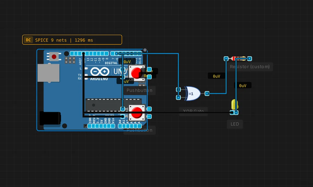
The exact circuit you get when you open this example — already wired, ready to run.
The sketch
// XOR — LED on when switches differ (physical XOR gate drives LED)
void setup() {
  pinMode(2, INPUT_PULLUP); pinMode(3, INPUT_PULLUP);
  pinMode(5, OUTPUT);       pinMode(6, OUTPUT);
}
void loop() {
  digitalWrite(5, !digitalRead(2));
  digitalWrite(6, !digitalRead(3));
}
How it works
Two switches on pins 2 and 3 are read with internal pull-ups (LOW when closed), inverted by the sketch, and driven onto pins 5 and 6 — the XOR gate’s two inputs. The physical gate compares them, and the LED on its output lights whenever the two inputs differ. The truth table is the circuit’s entire personality.
The loop is a two-line mirror: read both, invert both, write both. The gate does the actual logic in hardware — the MCU is only the signal conditioner between the switches and the gate, converting active-LOW switch states to active-HIGH gate inputs.
Before you build it for real
The inversion in the sketch is the classic trap: the switches are wired with pull-ups and read LOW when closed, so the code inverts with ! — get the polarity wrong and the XOR lights on agreement instead of disagreement. The gate’s inputs must be actively driven at all times: if the MCU is in reset, its pins float, and the XOR reads noise — a pull resistor on the gate inputs is the standard fix. And remember the XOR is a comparison, not a memory: it cannot tell you which switch moved, only that they differ.
Get the parts
Related examples
FAQ
What does XOR actually detect?
XOR (exclusive OR) is TRUE when its inputs are different — one HIGH, one LOW. Two switches in opposite positions light the LED; both ON or both OFF keeps it dark. It is the “they disagree” gate, and it turns any comparison between two binary signals into one output.
Why does the MCU read the switches instead of wiring them directly to the gate?
The physical XOR gate still does the decision — the MCU is the wiring: it reads the two switches and drives the gate’s two inputs. That arrangement lets the same physical circuit test any two signals, and the sketch’s inversion (!digitalRead) adapts the active-LOW switch wiring to the gate’s active-HIGH expectations.