
Zener Voltage Regulator
Zener Voltage Regulator is a runnable microcontroller simulation example on SensBench — open the wired circuit, inspect the code, and compile real firmware in your browser, no install needed. Last updated Aug 14, 2026.
FREE SIMULATOR EXAMPLE · INTERMEDIATE
Zener Voltage Regulator
This example demonstrates a 5.1 V zener voltage regulator on the Arduino Uno — a 9 V supply clamped to 5.1 V by the zener diode, with the Arduino reading the regulated output. The simplest voltage regulator that exists.
| Board | Arduino Uno (ATmega328P) + analog SPICE circuit |
|---|---|
| Difficulty | intermediate |
| Category | circuits |
| Libraries | None — just the Arduino core |
| Runs in | Sensbench browser simulator — free, no account |
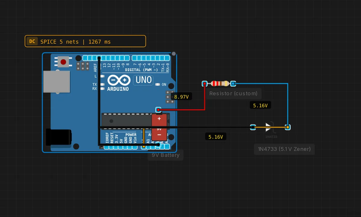
The exact circuit you get when you open this example — already wired, ready to run.
The sketch
// Zener 5.1V regulator
// Input = 9V battery, Rs = 220 ohm, Zener clamps to 5.1V
void setup() { Serial.begin(9600); }
void loop() {
  float v = analogRead(A0) * 5.0 / 1023.0;
  Serial.print("V_regulated = "); Serial.println(v, 2);
  delay(500);
}
How it works
The 9 V input meets the 220 ohm series resistor, then the 5.1 V zener clamps the node to ground. The zener breaks down in reverse and holds the node at 5.1 V — any extra input voltage is dropped across the resistor. The sketch reads the regulated node on A0 and prints it every 500 ms.
The reading should sit near 5.1 V and stay there while the input varies — the entire point of regulation. The comment states the design values, and the ADC readout is the verification: regulated voltage printed live, 2 decimals deep.
Before you build it for real
A zener regulator is wasteful by design: the series resistor always burns the input-voltage difference, and the zener burns whatever current the load does not take — at 9 V input and small loads, most of the input power becomes heat. The regulation is load-dependent: pull more than the resistor can supply and the output sags below 5.1 V. The zener voltage also has tolerance (±5%) and temperature drift, so the “5.1 V” output is really 4.9-5.4 V. And the ADC’s own reference (the 5 V rail) makes the reading relative — an interesting recursion when the thing being measured is the rail itself.
Get the parts
Related examples
FAQ
How does the zener hold 5.1 V?
In reverse bias, a zener diode breaks down at its rated voltage — 5.1 V here — and conducts just enough current to hold that voltage across itself. The series resistor absorbs the difference between the input (9 V) and the zener voltage, so the output sits at 5.1 V regardless of load or input variation.
Why 220 ohm for the series resistor?
The resistor must carry the load current plus the zener’s holding current while dropping the input-voltage difference: (9V - 5.1V)/220 = ~18 mA. That current is shared between the zener and the load — the zener takes whatever the load does not. Too large a resistor and the zener starves; too small and it wastes power as heat.