
Blog
Pico Multi-Protocol Demo: Four Buses, One Boot, One Hidden Bug

Every project in this Pico series exercised one thing at a time: a bus, a sensor, an LED. Real firmware isn’t like that — a data logger talks I2C to its RTC, SPI to its SD card, reads an analog battery gauge, and chats over serial, all in the same boot. This capstone example runs exactly that drill: one setup() that sweeps the I2C bus, writes and verifies an EEPROM byte, pings the RTC, runs an SPI loopback, reads the ADC, and finishes with three blinks. An integration smoke test, start to finish, in about a second.
It also ships with a genuine bug — in the RTC section, hiding behind a printout that says everything is fine. We’ll take it apart, because it’s the most instructive line in the whole series.
The circuit
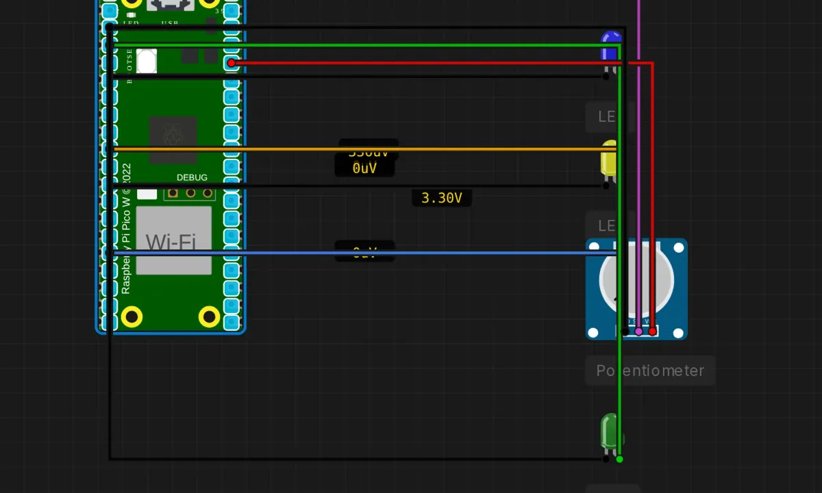
- Blue LED → GP12, yellow LED → GP7, green LED → GP2 (all cathodes → GND; all three labeled as protocol-activity indicators)
- Potentiometer → wiper to GP26 (A0), legs to 3.3V and GND
- The I2C devices (EEPROM at 0x50, DS1307 RTC at 0x68) are virtual — the simulator attaches them to the bus (SDA=GP4, SCL=GP5)
- SPI: no wiring — the loopback echo is internal
Veterans of this series can guess what I’m about to say about the three “activity indicator” LEDs. The sketch never drives them. Fifth example running. At this point I’m treating it as a deliberate personality trait of the series and simply pointing at it, once, here. The potentiometer, at least, is genuinely read.
The sketch
// Raspberry Pi Pico — multi-protocol smoke test
// One boot, four buses: I2C scan → EEPROM → RTC → SPI → ADC → blink.
// Everything runs once in setup(); loop() stays empty.

#include <Wire.h>
#include <SPI.h>

void setup() {
  pinMode(LED_BUILTIN, OUTPUT);
  Serial.begin(115200);
  delay(500);

  Serial.println("==============================");
  Serial.println(" Pico Multi-Protocol Demo");
  Serial.println("==============================");
  Serial.println();

  // --- 1. I2C bus scan: who's alive? ---
  Wire.begin();
  Serial.println("[I2C] Scanning bus...");
  int found = 0;
  for (byte addr = 1; addr < 127; addr++) {
    Wire.beginTransmission(addr);
    if (Wire.endTransmission() == 0) {
      found++;
      Serial.print("  Found device at 0x");
      if (addr < 16) Serial.print('0');
      Serial.println(addr, HEX);
    }
  }
  Serial.print("  Total devices: "); Serial.println(found);
  Serial.println();

  // --- 2. EEPROM: write 0x42 to cell 0, read back, verify ---
  Serial.println("[I2C] EEPROM test at 0x50...");
  Wire.beginTransmission(0x50);
  Wire.write(0x00);
  Wire.write(0x42);
  Wire.endTransmission();
  delay(5);   // write cycle time

  Wire.beginTransmission(0x50);
  Wire.write(0x00);
  Wire.endTransmission();
  Wire.requestFrom(0x50, 1);
  if (Wire.available()) {
    byte val = Wire.read();
    Serial.print("  Wrote 0x42, Read 0x");
    Serial.print(val, HEX);
    Serial.println(val == 0x42 ? " — OK" : " — FAIL");
  }
  Serial.println();

  // --- 3. RTC: is the clock alive? (see the bug discussion!) ---
  Serial.println("[I2C] Reading DS1307 RTC at 0x68...");
  Wire.beginTransmission(0x68);
  Wire.write(0x00);
  Wire.endTransmission();
  Wire.requestFrom(0x68, 3);
  if (Wire.available() >= 3) {
    byte sec = ((Wire.read() & 0x7F) >> 4) * 10 + (Wire.read() & 0x0F);
    byte min2 = Wire.read();
    (void)sec; (void)min2;   // values discarded — only the ACK mattered
    Serial.println("  RTC responded OK");
  }
  Serial.println();

  // --- 4. SPI loopback ---
  Serial.println("[SPI] Loopback test...");
  SPI.begin();
  SPI.beginTransaction(SPISettings(1000000, MSBFIRST, SPI_MODE0));
  byte tx = 0xAB;
  byte rx = SPI.transfer(tx);
  Serial.print("  TX: 0x"); Serial.print(tx, HEX);
  Serial.print("  RX: 0x"); Serial.println(rx, HEX);
  SPI.endTransaction();
  Serial.println();

  // --- 5. ADC: one channel ---
  Serial.println("[ADC] Reading analog channels...");
  analogReadResolution(12);
  int a0 = analogRead(A0);   // the pot on GP26
  Serial.print("  A0 (GP26): "); Serial.println(a0);
  Serial.println();

  // --- 6. Victory lap ---
  Serial.println("[GPIO] Blinking LED...");
  for (int i = 0; i < 3; i++) {
    digitalWrite(LED_BUILTIN, HIGH);
    delay(200);
    digitalWrite(LED_BUILTIN, LOW);
    delay(200);
  }
  Serial.println("  3 blinks done");
  Serial.println();
  Serial.println("=== All protocol tests complete ===");
}

void loop() {
}
Run it and the monitor narrates the whole drill: two I2C devices found (0x50, 0x68), the EEPROM byte verified, the RTC answering, one SPI byte echoed, the pot’s position in counts, three blinks. It feels like watching a board bring-up at a real bench — which is precisely what it is.
The bug that prints “OK”
Look hard at the RTC decode line:
byte sec = ((Wire.read() & 0x7F) >> 4) * 10 + (Wire.read() & 0x0F);There are two Wire.read() calls in one expression, and every call consumes the next byte from the buffer. So this line decodes the high nibble of the seconds register and the low nibble of the minutes register into something it calls sec. The next line reads a third byte — hours — into a variable named min2. Every register lands one position off, and the “seconds” value was never correct to begin with.
And it gets subtler: in C++, the evaluation order of the two operands of + is unspecified. The compiler may evaluate either Wire.read() first. The line isn’t just wrong — it’s wrong in a way the language standard declines to pin down. Two side-effecting calls in one expression is the mistake; the BCD math is a distraction.
Why did nobody catch it? Because of the next line: (void)sec; (void)min2; — the values are discarded. The test only verifies the RTC acknowledged, prints “RTC responded OK,” and moves on. The bug is invisible in output, so it survives. If you take one habit from this article: one Wire.read() per statement, store the byte, then do the math. The correct version is three boring lines — boring being the highest compliment in driver code:
byte secRaw = bcdToDec(Wire.read() & 0x7F);
byte minRaw = bcdToDec(Wire.read());
byte hrRaw  = bcdToDec(Wire.read() & 0x3F);
Honest notes on the rest
- The ordering deserves praise. Scan the bus first, then address specific devices — that’s the correct bring-up sequence, and this sketch models it. When the scanner prints your expected addresses, every failure after that point is logic; when it doesn’t, every failure is wiring. Knowing which universe you’re debugging in saves hours.
- The SPI section is honest about its limits. No MOSI–MISO jumper exists in this example, and the source admits the read may return 0xFF. On the sim it echoes internally; on hardware, expect 0xFF and treat that as “bus alive, nothing attached,” which is itself a valid result.
- Everything in
setup(), emptyloop()— the right shape for a power-on self-test, and it has a name in industry: POST. Boot, test every peripheral once, report, proceed. The three blinks at the end are your “all tests passed” indicator for anyone watching the board instead of the serial monitor. - What this doesn’t test: concurrency. The protocols run sequentially, one per section. The genuinely hard version — I2C transactions while SPI transfers while ADC sampling, without blocking — needs the
millis()discipline from the serial echo project, and eventually DMA or the RP2040’s second core. This demo is the tour, not the marathon. - One LED gets driven; three don’t. The blinks use the onboard LED. The three wired indicators remain furniture. Fifth time in the series; the four-line fix from the scanner article works here too, and at six blinking opportunities it’s arguably worth it.
When a section reports failure
- “Total devices: 0” → the virtual chips didn’t attach (reload the example) — or on hardware, the whole bus is dead: SDA/SCL, power, pull-ups.
- Scanner finds devices but EEPROM read is 0xFF → bus works, device logic doesn’t: wrong address in the code, or the write hasn’t had its 5 ms.
- SPI prints DIFFER / RX=0xFF → no loopback jumper (real hardware) — expected, not a failure. Knowing which “failures” are by design is half of reading a test report.
- A0 reads garbage with the pot attached → wiper not on GP26, or the pot’s outer legs aren’t on 3.3V/GND. (And if it reads garbage with nothing attached — that’s floating, see the ADC project.)
Where to go from here
This sketch is a template, and the intended use is your own hardware: steal the structure, replace each section with your actual peripherals, and run it as the first firmware on every new board you bring up. Extend it by making the loop non-empty — heartbeat on serial, sensor polls on a millis() schedule — or by wiring the three status LEDs for real so the board reports which bus is busy without a monitor attached. The Pico series ends here; everything after this is just these blocks, composed.
Open the simulator and load the Pico multi-protocol example. Watch the full bring-up sequence narrate itself — then find the RTC line and fix it properly. One Wire.read() per statement. You’ll recognize the bug on sight the next time you meet it, and it won’t be in a tutorial then.