
Blog
Blink an LED on Arduino in Your Browser — No Board Needed

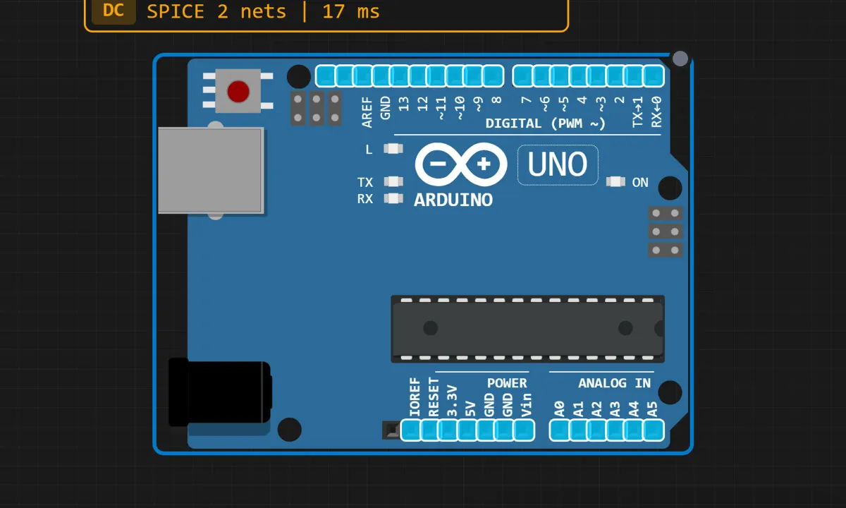
Everyone’s first Arduino project is the blink sketch. It’s the “Hello, World!” of microcontrollers, and there’s a reason it has survived decades: it proves your board works, your code runs, and your wiring does what you think it does — all with one little LED.
Here’s the part most tutorials won’t lead with: you don’t need to buy anything to learn it. You can build and run the whole thing in a browser simulator, watch the LED blink, and only order a board once you actually understand what’s happening. That’s what we’ll do here. I’ll also tell you where the simulation stops matching reality, because it does.
The circuit is the board
Most “build a circuit” tutorials start with a parts list. This one doesn’t, because the Arduino Uno already carries the whole circuit on its PCB: a small LED (marked L) is hard-wired to digital pin 13, with a current-limiting resistor sitting in series on the board itself. Nothing to plug in, nothing to solder, nothing to burn out.
If you later move to a real board and want an external LED instead of the onboard one, the recipe is: anode (the long leg) → pin 13 through a 220Ω resistor, cathode (short leg) → GND. Anything between 220Ω and 1kΩ works; lower values make it brighter and angrier. But for now, keep it simple.
Getting the board onto the canvas
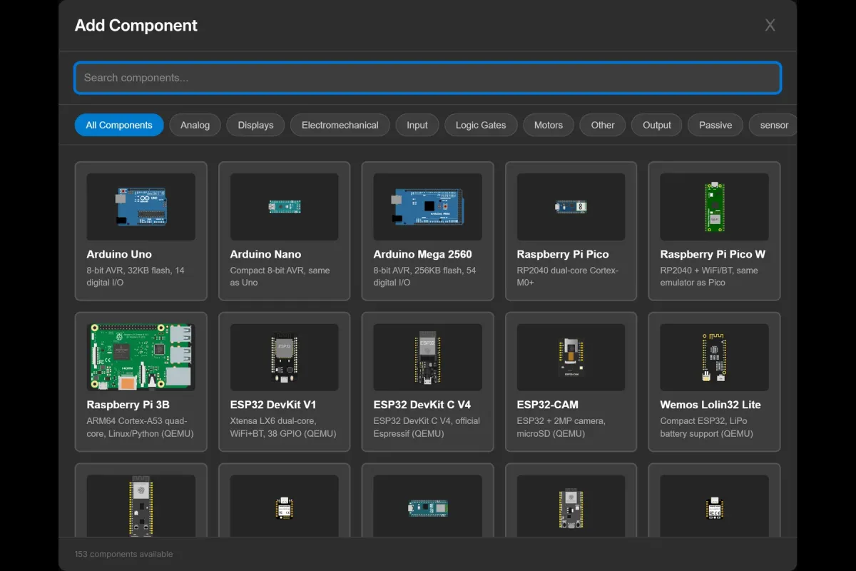
Open the simulator and click Add (or the Components button, depending on the view). A component picker pops up with a search box and a grid of boards. Type “Arduino Uno”, drag it onto the canvas, done.
The board lands on the canvas with its pin labels visible. Find the L marker next to pin 13 — that’s your LED. It won’t look like much until the simulation is running.
The four lines that matter
Click over to the code editor. This is the entire sketch:
// Blink: toggle the onboard LED once a second

void setup() {
  pinMode(13, OUTPUT);
}

void loop() {
  digitalWrite(13, HIGH);
  delay(1000);
  digitalWrite(13, LOW);
  delay(1000);
}
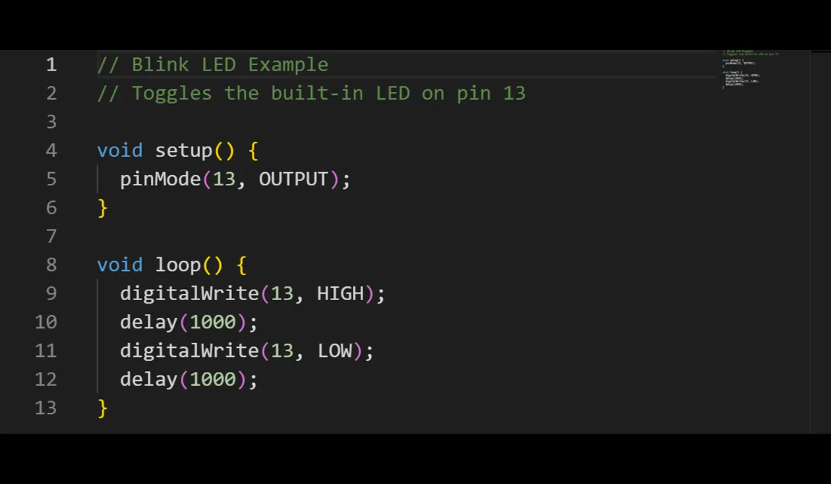
Arduino sketches always have two functions. setup() runs once at power-up; loop() then runs forever, top to bottom, over and over. Inside them, four lines do all the work:
pinMode(13, OUTPUT)— tells the chip that pin 13 is for sending voltage out, not reading signals in. Skip this and the pin stays an input; the LED may glow faintly or not at all, which confuses everyone the first time.digitalWrite(13, HIGH)— pushes the pin to 5V. LED on.delay(1000)— sits there doing nothing for 1000 milliseconds. Without it the LED would flicker millions of times per second and look solid to your eyes.digitalWrite(13, LOW)— drops the pin to 0V. LED off, then the seconddelay(1000)holds it there before the loop repeats.
That’s genuinely the whole program. If this feels anticlimactic, good — that’s the point of blink.
Hit Run
Press the Run button in the editor toolbar. The simulator compiles your sketch and starts executing it on a virtual AVR chip — the same family that’s on a real Uno.

Watch the L LED on the canvas: one second on, one second off. The canvas toolbar also gives you pause, stop, and reset, plus a serial monitor and an oscilloscope you won’t need yet but will soon.

What the simulator won’t tell you
A simulation is a kind teacher, but it skips a few lessons that real hardware teaches immediately:
- LEDs don’t die in simulators. Wire a real LED straight to a pin with no resistor and it will work — briefly. Then it burns out, or slowly damages the GPIO. The simulator happily runs that circuit forever, so build the resistor habit now.
- Real Unos blink at boot. The bootloader flashes the L LED a few times when the board powers up. Beginners regularly mistake this for their code misbehaving. It’s normal.
- Clone boards vary. On cheap Uno clones the L LED might be a different color, dimmer, or on a slightly different pad. The sim shows you one idealized board; your desk drawer won’t.
delay()blocks everything. In this sketch that’s fine. In a real project with buttons or sensors, those frozen 1000ms become a bug. Remember the feeling of “why won’t it respond while it’s delaying” — it’ll come back around.
Mistakes that cost people time
I’ve watched a lot of first sketches fail. It’s almost always one of these:
- No
pinMode()insetup(). The classic. Everything compiles, nothing lights. - External LED plugged in backwards. Long leg to the pin, short leg to ground. Reversed, it just stays dark — no damage, no light, no fun.
- Editing the code but never pressing Run again. The simulation doesn’t restart itself.
- Typing the pin as a letter or grabbing pin 12 by habit. The onboard LED only listens to pin 13.
Where to go from here
Once the 1-second blink feels boring — which takes about two minutes — start changing things. Drop the delays to 250ms and watch it strobe. Move an external LED to pin 12 with its own resistor and rewrite the sketch to match. Try analogWrite() on a pin marked with a ~ (those are the PWM-capable ones) and fade the LED instead of toggling it. Or add a pushbutton and make the LED answer to your finger.
Open the free simulator and load the Blink example — the circuit and code from this article are already wired up. No account, no install. When the LED blinks back at you, you’re officially an embedded programmer. Sort of.